PerkinElmer Series 200 HPLC SOP
Primary Equipment:
HPLC
Created: February 22, 2010 by Bob Cox
Revised: February 24, 2010 by Bob Cox
University of Utah, Chemical Engineering
Equipment Overview:
This document outlines the basic procedure for using the Sedex light scattering detector and the PE series 200 HPLC system to detect sugars. To use this system to detect and analyze other compounds consult the lab manager.
This system is comprised of the following components (Figure 1):
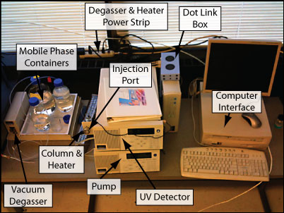
Figure 1: HPLC System.
Series 200 pump, UV/VIS detector, SEDEX Light Scattering Detector, Vacuum Degasser, Column Heater, Phenomenex Luna 5 micron NH2 column.
The column is operated in reverse phase using a mixture (mobile phase) of 80% acetonitrile and 20% water. The UV/VIS detector is not normally used to detect sugars.
Safety:
Acetonitrile is highly toxic. Gloves and safety glasses must be worn while operating this equipment. Prior to operating this equipment please read the MSDS for acetonitrile located in this document. Filling or emptying the mobile phase bottles must be done in the fume hood.
Pre-Operation Checklist:
- Safety Glasses and gloves must be worn when operating this equipment.
- Before operating this equipment review all safety data specific to the chemicals you will be using. M.S.D.S documents for acetonitrile and methanol are located in the back of this book.
- Prepare samples and reagents before powering up the HPLC.
- All samples must be labeled with content, date and owner information.
- Select the 25 micro liter HPLC injection syringe and 0.45 micron filter located in the HPLC supplies container.
- Check in with lab personnel to review operating procedure before operating this equipment.
- Make certain the mobile phase bottles (A = water), (B = ACN, acetonitrile) are at least half full, if they are less than half full contact the lab manager.
- Filter all samples through a 0.45 micron syringe filter prior to injecting the sample into the HPLC column. Note, the injection loop volume = 20 micro liters, this is the maximum injection volume.
- Do not adjust the front panel controls on the SEDEX detector.
- Do not modify this equipment without prior approval from laboratory staff.
The following instructions refer to the block diagrams on the TotalChrom main window (Figure 2).
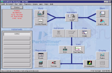
Figure 2: TotalChrom Main Window.
Startup:
- Turn on the computer and log on as posted on the computer monitor:
- Apply power to the HPLC system in the order listed below:
- Turn on power strip located just to the right of the feed bottles. This applies power to the column heater and the vacuum degasser.
- Turn on the series 200 UV/VIS detector; the switch is located on the back of the unit above the power cord.
- Turn on the series 200 pump; the switch is located on the right side of the pump.
- Turn on the Sedex 55 detector; the switch is located on the right rear of the unit.
- Allow the column heater to run for 10 minutes before injecting samples.
- Make sure the mobile phase waste container is secured next to the SEDEX (Figure 3).
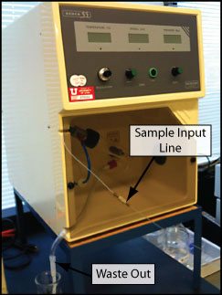
Figure 3: SEDEX Light Scattering Detector.
- Verify that the lights on the dot Link box – located on top of the NCI 900 box to the right of the series 200 pump/detector � are displaying green LED�s for the A, B and F locations. If this is not the case consult the lab manager.
- Open the Total Chrom Software:
- Double-click on the TCNav icon on the desktop.
- Using the drop-down menu select manager as the user name. Enter Chrom as the password. Click OK.
- Create data folders.
- TotalChrom saves two types of data files; RAW and RESULTS. It is good practice to keep these data types in separate files. Create a file folder for each type of data as follows:
- Navigate to C:STUDENT HPLC DATA, and create a folder in this location for your RAW data.
- Use a unique name that identifies the data type, example (Raw data Group 1); create a second folder for the RESULTS data with a similar name, Ex (Results data Group 1).
- Configure the software:
- In the instruments window select SEDEX then click on the RUN icon located in the lower center of the screen. Select CLEAR SETUP if it is not grayed out, if it is, proceed to the next step and confirm the clear setup command. If the setup is cleared proceed as follows. Wait until the Status window, located on the upper left hand of the display, indicates the setup has been cleared; the setup window should display �SEDEX � No Method�.
- Load the sequence for the SEDEX light scattering detector. In the INSTRUMENTS window on the left side of the display select the SEDEX button then select the INSTRUMENTS / SETUP box in the upper center of the display. The Setup Instrument window should be displayed. Select SEQUENCE at the top of the window. Then click on the folder icon to the right of the sequence dialog box.
- After clearing the SETUP click OK to close the Setup Instrument Window. Note the status window will momentarily display �SEDEX Ready�. If this message is not displayed contact the lab manager.
- Navigate to C: Student Sequences and Methods. Select SEDEX � SUGARS SEQUENCE 2-25-09, click select, do not close the dialog window.
- Check the (Store data in the above paths �) box. The starting and ending row values default to 1 and 30 respectively. This defines the number of samples you can run before you must start the software again. Do not change these values!
- Select the RAW DATA path folder and navigate to the location of your RAW data folder � the one you created earlier – for the Sedex data. Click OK. This path should now be displayed in the raw file path dialog window.
- Select the RESULTS DATA path folder and navigate to the location of your RESULTS data folder for the Sedex data. Click OK. This path should now be displayed in the results file path dialog window.
- Click OK. You have just defined the locations for your RAW and RESULTS data.
- Observe the Status window in the upper left had corner of the display, it should display a setting up message then, after a slight delay SEDEX ready will be displayed.
- Configure the PE Series 200 LC pump:
- Under the instruments window on the left side of the display select the PE Series 200 LC.
- The status window should display the �PE Series 200 LC No Method��
- Click the RUN box then select Take Control.
- After a slight delay the status window will display �Seizing� then �PE Series 200� No Method ��Pump Off.� This completes configuration of the pump. The pump flow rate has been preset. If you want to change the flow rate consult the lab manager. If a SEIZING ERROR is displayed cycle the power on the pump and the UV detector then repeat from step 6-C. If the seizing error returns contact the lab manager.
- For the detection of sugars the UV/VIS detector is typically not used. If you would like to configure the UV/VIS detector and run it in series with the Sedex light scattering detector proceed to the next section. If you will be running only the Sedex detector, skip the next section.
- Configuring the UV/VIS detector:
- The UV/VIS detector utilizes a tungsten lamp (visible)(Wavelength 360 � 700 nm) and a deuterium lamp (UV)(Wavelength 190 � 360 nm). The detector operates using one lamp at a time. The detector is normally set-up for operation using the UV lamp. The current method sets the wavelength to 238nm. If you wish to use the visible lamp contact lab personnel. Note that the UV/VIS detector is not used to detect sugars.
- Verify that the PE Series 200 LC is selected in the instrument window on the left side of the screen.
- Select the Instrument Setup box in the center of the screen. Select Sequence. Click on the sequence folder to the right of the sequence dialog window.
- Navigate to C: Student Sequences and Methods.
- Select UV VIS Sugars SEQUENCE 2-26-09.
- Check the �Store data in above paths ��box.
- Click on the folder icon to the right of the Raw File Path dialog box, select the RAW DATA path folder and navigate to the location of your RAW data folder for the UV/VIS data � not the SEDEX data.
- Click on the folder icon to the right of the Results File Path dialog box, select the RESULTS DATA path folder and navigate to the location of your RESULTS data folder for the UV/VIS data. Don�t store SEDEX data and UV/VIS data in the same folder.
- Confirm starting and ending rows are set to 1 and 30 respectively. Click OK.
- The status window will briefly display a �Setting Up� message, then �Ready�. This completes the setup for the UV/VIS detector.
- Open the main valve on the UHP nitrogen cylinder (Figure 4).
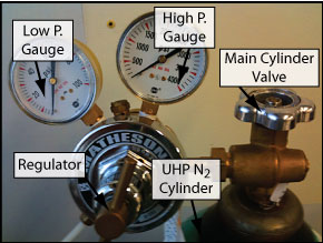
Figure 4: Valves Associated with the Nitrogen Cylinder.
- Verify that the high pressure gauge on the nitrogen cylinder reads a value greater than 500 PSI.
- Verify that the low pressure gauge reads approximately 30 PSI.
- Verify that the pressure display on the Sedex light scattering detector reads 2.0 Bar.
- If the pressure display on the Sedex does not read 2.0 Bar consult the lab manager.
- Sample preparation and column flush procedure:
- Filter all samples through a 0.45 micron syringe filter prior to injecting the sample into the HPLC column. This will prevent clogging the column. If the column becomes clogged it is unlikely that it can be cleared. A new column will be required at a cost in excess of $600.00.
- Prior to injecting samples you must flush out the column by running a blank sample. A blank sample should be run each day before starting your sample runs.
- Running a Blank:
- Follow the sample injection procedure listed below but do not inject anything into the sample loop.
- When running a blank sample, allow the system to run for the full 20 minutes. Running a blank will help limit the number of false peaks.
- Sample Filtration:
- Using a Syringe filter sample the yeast material through a 0.45 micron syringe filter into a 3 – 10 ml syringe. Then inject the filtered yeast solution into a clean, small beaker.
- You will fill the HPLC injection syringe from this beaker. This procedure insures that all solution injected into the HPLC has been filtered.
Sample Injection Procedure:
- Verify that the injection valve on the series 200 pump is rotated counter clockwise to the eight o�clock position (Figure 5).
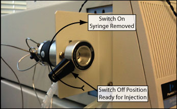
Figure 5: Injection Valve.
- In the instruments window click on the PE Series 200 LC.
- Open the Hands On dialog box.
- Click on Start Pump.
- Close the LC Hands On Dialog box.
- Draw filtered sample into the 25 micro liter PerkinElmer injection syringe.
- Insert the needle on the injection syringe into the injection port as illustrated below.
- Inject sample into port and remove syringe.
- Rotate the injection valve on the series 200 pump to the right until it stops at approximately the 10 o�clock position. Rotating the injection valve to the right will start the run.
- Wait 30 seconds to allow the sample to flow through the sample loop then turn the injection valve back to the left until it stops at the 8 o�clock position.
- You will notice the preset flow rate displayed on the pump module reads 2.00 mL/min.
- The run time is preset to 20 minutes. At the end of the 20 minute run the pump will automatically reduce the flow rate from 2 ml/min to 0.5 ml/min.
Viewing the chromatogram in real time:
- Click on the Real-Time Plot icon on the desktop. This will open a window displaying the graph of the run.
- You may adjust the scale of the graph by clicking on Options ? Rescale or by manipulating the icons at the top of the window.
- Allow the run to go the full 20 minutes to flush out the column.
- If you are running the UV/VIS detector in addition to the SEDEX detector you can observe both graphs by selecting the Window tab at the top of the Real-Time Plot and selecting the desired view.
Interrupting the Run:
- To stop the current run select the Run tab from the SEDEX Real-Time plot and then select Stop Run.
- If you select Cancel Run the data will not be saved.
- You must stop the run for all detectors you are running. If you are running the UV-VIS detector open the Real-Time Plot for the UV VIS detector and stop the run for that detector as well as the SEDEX detector.
Stopping the Pump:
- After stopping the run, stop the pump by opening the Real-Time plot for the UV/VIS detector, select RUN from the top of the display and then select STOP PUMP.
- Alternatively, Minimize the Real-Time Plot, Select PE Series 200 LC in the instruments window. Click on the HANDS ON box in the center of the screen and select Stop Pump.
Starting another run after interrupting a run:
If you have stopped a run before it is completed you must repeat steps 5G and 5H to reassign the data files for the detectors you are using (SEDEX and/or UV-VIS)
- Confirm that the injection valve is rotated all the way to the left.
- Select the PE Series 200 LC in the instruments window.
- Open the HANDS ON dialog box and select Start Pump.
- Select the SEDEX detector in the Instruments Dialog box.
- Repeat the injection procedure as outlined in step 11.
Running repeated samples:
After the 20 minute run period is complete the pump will automatically reduce the flow rate from 2.0 mL/min to 0.5 mL/min.
To continue injecting samples:
- Rotate the injection valve counterclockwise to the 8 o�clock position.
- Verify that your sample has been properly filtered as outlined in step 11.
- Fill the injection syringe with the sample. Remember that 20 microliters is the maximum injection volume.
- Inject the sample.
- Rotate the injection valve clockwise to start the run.
- Repeat these steps for up to 30 injections. If you require more that 30 runs in a single session you will be required to restart the software from step 4.
Viewing Chromatograms:
- Open the Chromatogram dialog box. Select File � Open.
- Navigate to your RAW DATA folder and select the file you wish to open.
- Note that the files are date and time coded. Open your RAW data file.
- Repeat these steps for the RESULTS data. _Select the results file folder and the results file data type in the drop down menu.
- Be sure to open the same RAW and RESULTS files, don�t open one run in RAW format and a different run in RESULTS format.
- Both raw and results chromatograms should now be visible. As you move the cursor over the graph, the bottom left of the screen displays which file type you are viewing. The results file contains retention times.
- To expand a section of the chromatogram left click and drag over the area of interest.
- To undo the expansion right click and select undo.
- Note the other menu options available by right clicking.
- To copy the chromatograph to a word or Excel file select File-Copy to Clipboard.
- All data is automatically saved in the raw and results files you created earlier.
- Data files are date coded.
Editing chromatograms and reprocessing data:
The reprocessing software allows the user to edit the chromatogram. Editing options are extensive and include removing excess peaks and editing baseline data.
Eliminating unwanted peaks:
- Double-click on the Results icon located on the lower right side of the desktop.
- Go to Process ? noise area threshold, right hold click and drag the mouse over an area of the graph � the noise /area threshold dialog box will open � to eliminate many of the false peaks enter a number larger than the current value in the �suggested NT� box.
- If you are unhappy with the results, left click to return to the original display then try again until you find a noise threshold value suitable for your graph.
Printing Chromatograms:
- Select the print function from the top menu.
- The data is sent to the printer located in the computing lab adjacent to the senior lab.
- Copy your data to a flash drive after each session.
Shut Down:
- Close main cylinder valve on Nitrogen Tank (Figure 4).
- Click on the PE Series 200 LC in the instruments window.
- Click on the Hands On window located in the center-left of the screen.
- Click Stop Pump ? close.
- Exit the software.
- Turn off the power to the pump, SEDEX detector and UV/VIS detector.
- Turn off power strip located just to the right of the feed bottles. This applies power to the column heater and the vacuum degasser.
- Cleanup work area, label and properly store samples and mobile phase.
- Rinse syringe in D.I water, place syringe in storage box.
Troubleshooting Tips:
- PE Series 200 status reads No Method, cannot start the pump: Try selecting the PE Series 200 in the Instruments window then open the RUN window, select Take Control. Wait for the seizing message to clear and then open the Hands On dialog box and select start pump.
- Status errors when booting system: Cycle the power to all hardware including computer. Repeat power-up sequence.
- Pumps stops before run is completed: Consult lab manager.
- Status window displays �unknown instrument�: Note that this message is often displayed for up to one minute until the software recognizes the hardware at which point the message is cleared. Close Total Chrom, then cycle power to the Dot Link box by removing the power cord to the box, wait 30 seconds then insert the power cord on the Dot Link box. Start Chrom Perfect and try again.