UOL Multiple Continuous Stirred Tank Reactor (CSTR) SOP
Standard Operating Procedure
Introduction
There are several CSTRs in different laboratories. This SOP focuses on the three CSTRs in series module (see Figure 1).
Do not proceed with testing without following all safety procedures. A basic list of safety considerations is provided in Section II of this SOP.
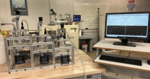
Figure 1. CSTRs in series. The pumps are located to the left. See also Figure 2. Notice the digital displays for conductivity measurements in each reactor.
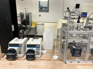
Figure 2. Ancillary pumping equipment and feed.
Safety
- All students must wear safety glasses when working in the lab.
- Never leave this equipment operating unattended.
- Mix all chemicals in a fume hood.
- All chemicals, solutions, and standards must be stored in a sealed container. The container must be labeled with chemical(s) name and concentration, operator/user’s name, hazards, and date of storage. Confirm storage location with the lab manager.
- All chemical containers must be sealed when not in use.
- All unwanted material must be placed in an appropriate container. The container must be labeled “Unwanted Material”. The label must include the chemical(s) name and concentration, the operator/user name, contact information, and hazards. If you have questions regarding labeling unwanted materials, see the sign posted above the unwanted materials table in the Senior Lab.
- Only pure water can go down the drains.
Equipment Description
The CSTR experiment consists of the following components.
- MasterFlex peristaltic pumps: These pumps have a switch on the rear panel. Each pump must be set to external for the computer system to control the pumps (Figure 2).
- Three acrylic reactor vessels, each with a maximum volume of about 2 L. Each tank has an independent stirring system.
- Opto22 Control System:
- Data are sampled every second and stored in an Excel-compatible file in a folder labeled “data” (or similar) on the Desktop of the computer used with the apparatus. See the section on viewing your data for more information. Save your data to a flash drive. The computer is not on the network.
- Sensorex conductivity measurement system (Refer to Figure 3 – readout devices may vary).
- The conductivity range is 0 to 19.9 millisiemens with a resolution of 0.01 millisiemens. Optional equipment includes pH and UV-Vis meters that you may sometimes use to assess the reaction. See the lab manager for more information.
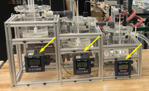
Figure 3. Three Sensorex conductivity sensors are denoted with yellow arrows for each CSTR. Note where the measurement is made in each tank.
CSTR Procedures
- Take detailed notes during your experiments, documenting failed and successful tests. Have a supplementary written record with start and stop times and descriptions of individual experiments so that you can later “decipher” recorded data.
- Determine what chemicals, calibration standards, and measurements you will need to make.
- Determine the desired inlet flow rate for your solutions reactants.
- Depending on the pump specifications determine what tubing is appropriate for your flow rates. Be sure to use only MasterFlex tubing. If you are unsure about which diameter tubing to use, check with the lab manager. The smaller the inner diameter of the tubing the lower the flow rate you can achieve.
- Pumps (flow rate) may/should be calibrated with a graduated cylinder/calibrated bucket and a stopwatch. Calibration can either be done using RPM (Internal pump controls), or percent power (External pump controls-using Opto22 control interface).
- Install the tubing through the peristaltic pumps. Depending on the model of peristaltic pump being used, it may be possible to use the same size tubing in both heads of a dual–head pump to achieve two identical flow rates – but you should calibrate each pump, nonetheless.
- Place the reactant feed tubing into the reactor. Ensure that the other end is connected to the fitting on the top of the initial CSTR reactor (on the left in the figures above).
- Ensure that the “outlet” of each reactor is connected to the appropriate conductivity sensor and/or feeds into a proper waste container (after passing through the third CSTR.
- You will measure conductivity and use that to determine the concentration in each tank. First, confirm that the meter is correctly calibrated by running a standard. Then, measure the conductivity of known concentrations of your product (see Item 11).
- Power up all equipment (the computer should be on):
- Pumps: Switch on the power to the pumps by using the grey toggle switch located on the front panel for older pumps or the power switch in the back for newer pumps.
- Impellers: Switch on each of the impellers by inputting a desired percent power into the Opto22 interface.
- The Sensorex conductivity module does not have a switch, it is always on.
- Do not touch the Opto22 control hardware located behind the reactor.
- Using the conductivity measurement system:
- The conductivity probe is fitted through the top of each reactor vessel. This probe connects to the conductivity transmitter (Sensorex Model CX 105) mounted on the CSTR frame.
- The probe is set at the correct depth. If you need to remove the probe to calibrate your solution (step 12), pay attention to the depth of the probe before you remove it so you can put it back to the same depth.
- Do not attempt to adjust the calibration setting on the CX105 conductivity meter. You can verify if the conductivity system is working properly by using the provided conductivity standard. (Following the protocols 12b to 12d). Consult the lab manager if you feel that the meter requires adjustment.
- Calibrating chemical solutions:
- In addition to testing the reliability of each conductivity meter using the standard, you will need to prepare individual concentrations of your reactants and products, and then use the conductivity system to build a calibration curve of concentration versus conductivity. Follow the procedures outlined below, for each conductivity meter.
- Disconnect the conductivity probe by unscrewing the top black fitting. The probe now can be removed from the top lid of the reactor.
- Place the probe in the solutions that you have prepared for calibration or in the standard that you are using to confirm the reliability of each sensor – Refer to Figure 4. Make sure to rinse the probe with DI water between different solutions.
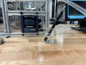
Figure 4. Conductivity probe in a solution.
-
- After the calibration curves are obtained and you have also tested system reliability with the standard, you can re-install the probe through the top lid of the reactor. There is a set of O-ring seals that needs to be installed in the correct order. Please check Figure 5.
- Repeat for each tank.
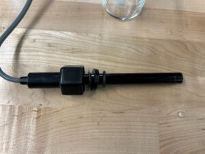
Figure 5. Set of O-ring seals on the conductivity probe.
13. See the lab manager for assistance with other measuring devices such as pH and UV-Vis that might be used under certain circumstances.
14. Determine the amount of feedstock you will require.
15. Mix all chemicals/feedstock dilutions in a fume hood.
16. Place your feedstock in 8-liter Nalgene containers available in the “A” lab on the shelf above the chemical storage cabinets (MEB 3520 A).
17. Feed the outlet stream of the system into another Nalgene waste container.
18. Verify that the feed and drain pumps are connected properly.
19. Weigh your solutions.
How to View and Save Data in Excel
- Do not try to view your data while the system is running. This will cause it to stop data collection.
- Save data to a flash drive after each trial.
- If you have any questions, ask for assistance.
If you are running one trial:
- Once all your required data have been collected, exit the Opto system.
- Open Excel, click “Open” and navigate to the correct data folder on the desktop (labeled “Data” or something similar).
- At the bottom of the Excel window, click on the drop-down window and select “All Files”. This will display the data files collected, organized by date.
- Double-click on the file you wish to open. The Text Import Wizard will open.
- Select Delimited. Then click Next. Then select Comma Delimited and click Next. Select the General Data format option and click Finish. The data should now be displayed in Excel
- Save your data to a flash drive by clicking “Save As” and selecting your flash drive as the destination. Ensure that you label your data properly and thoroughly to avoid confusion.
- Eject the flash drive.
- Follow the rest of the shutdown procedure specified in the equipment SOP (see the section labeled Shutdown, below).
If you are running several trials in one day:
- Leave the Opto system running.
- Open File Explorer and navigate to the correct data folder, on the desktop (labeled “Data” or something similar).
- Organize/sort by date if you have not already done so. Your data should appear at the top of the list.
- Right-click on your data file and “cut” the file (or press Ctrl X after clicking once on the file).
Note: this will effectively cut the data that were collected up to that point into a file and begin a new data collection (a new file will be created with the same name as the file you cut) as soon as it is cut.
- Paste the cut file to a flash drive and rename it with a proper label. Ensure that you are labeling your data thoroughly to avoid confusion.
- Eject the flash drive and save it to your personal device.
To open in Excel on your personal device:
- Open Excel. Next, click File/Open and navigate to the saved data on your flash drive or device.
- At the bottom of the Excel window, click on the drop-down window and select All Files. This will display the data files collected, organized by date.
- Double-click on the file you wish to open. The Text Import Wizard will open.
- Select Delimited. Click Next, select Comma Delimited, and then click Next. Select the General Data format option and click Finish.
Shutdown
- Pump DI water through the system until the conductivity meter reads <100 microsiemens. Store any solution you wish to save in a properly labeled Nalgene container. Consult the lab manager regarding chemical storage.
- To empty the CSTR reactor, insert a piece of tubing connected to a pump into one of the holes on the top of the reactor, pump the solution/water out, and dispose properly.
- Label all containers, following appropriate labeling protocols.
- Properly dispose of any unwanted material. Consult the lab manager for guidance.
- Set the impeller’s power to 0.
- Switch off the power to the pumps. Either place the toggle switch in the center for older pumps or flip the power switch on the back of the pump for newer pumps.
- Do not attempt to switch off the Sensorex conductivity module.
- Exit the Opto control software. Do Not Shutdown the Computer.
- Save your data to a flash drive. The computer is not on the network.