MPTL Fluid Flow Bench SOP
Standard Operating Procedure
Acknowledgements
The Fluid Flow Bench was designed and built by the members of SPQ Engineering. These are Sammy Partridge, Porter Nelsen, and Quayde Garfield, Class of 2023. None of this project would have come to be without the generous help of Dr. Thang Tran who was instrumental in the procurement and supervision of the project. We also wish to acknowledge the Department of Chemical Engineering for funding this project, and for allowing 3 students to destroy an older FFB, and having faith that it could be reconstructed efficiently. We are grateful for the experiences that we have had throughout the design and construction of the FFB, and hope that it will continue to serve students for years to come.
Safety:
- All students must wear safety glasses when working in the lab.
- Never leave this equipment unattended while operating.
- Never operate the pump with all valves closed. Valves for a specific pipe section must be open for operation.
- Be aware of any spills that may occur, and coordinate to clean them up as quickly as possible.
- Be aware of any contact between electricity and water, as a shock hazard exists.
- Mix all chemicals in a fume hood.
- All chemicals, solutions and standards must be stored in a sealed container. The container must be labeled with the chemical(s) name and concentration, the username or group name, and the date it is stored in the container.
- All chemical containers must be sealed when not in use.
- All unwanted material must be placed in a Nalgene container. The container must be labeled “Unwanted Material” the label must include: the chemical(s) name and concentration, the username or group name, and the date it is stored in the container.
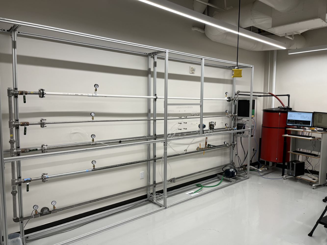
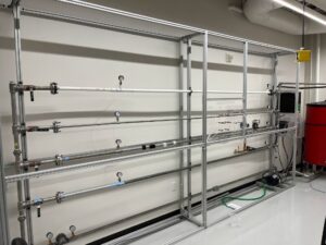
Equipment Description:
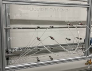
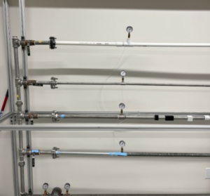
The Fluid Flow Bench (FFB) located in MEB 2550 is equipped with 4 pipe sections. These pipes are as follows:
- 1 inch, Schedule 40 PVC
- 1 inch, Schedule 40 Stainless Steel
- 1/2-inch, Schedule 40 Stainless Steel
- 1 inch, Schedule 40 Galvanized Steel (Corroded)
Each pipe section comes with 2 pressure gauges for measuring the pressure drop along the length of pipe. There are permanently mounted ball valves, that allow for the diverting of water through the desired pipe length.
Additional equipment is included, as follows:
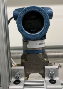
- Pressure Transducers
- Rosemount 1FT609, range 0-200 inches of water (see below)
-
- Dwyer Model 629, range 0-25 PSI (see below)
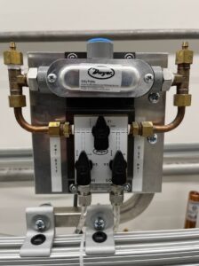
- Dwyer Model 629, range 0-25 PSI (see below)
- Rosemount 1FT609, range 0-200 inches of water (see below)
- Flow meter
- Omega Engineering Model FPR-200 paddlewheel type flowmeter, range 0-50 GPM (see below)
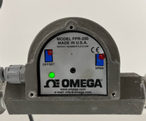
- Omega Engineering Model FPR-200 paddlewheel type flowmeter, range 0-50 GPM (see below)
- Pump
- Motor: Leeson 2 HP, 3450 RPM, 3 Phase.
- Pump head: Finnish Thompson Inc., AC/AV Max Pressure 100 PSI.
- Tank
- 3 feet in diameter, approximately 4 feet high, with a volume of approximately 250 gallons.
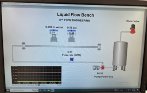
- Software
- PAC Display Runtime Pro.
Further details on select pieces of equipment are included at the end of the SOP.
General Operation:
Startup:
- Ensure that the tank is full of water, such that the recirculation pipe is covered with water. If the pipe is not covered, air will enter the system, and cause issues. Water can be added to the tank by turning on the ‘Water Valve’ using the PAC Display Runtime Pro.
- Open all valves in the FFB and set pump power to 100%. Turn on the pump.
- Disconnect the male end of the quick connect from the pressure transducer. Lightly pressing the tip of the quick connect will allow water and air to exit the FFB. Using a cup, drain tubing until all air is evacuated from the tubing. Repeat with all other pipe sections.
- ALL AIR NEEDS TO BE BLED FROM THE FFB FOR ACCURATE DATA.
- Turn off the pump and close all valves with respect to the pipe lengths.
- Before turning on the pump, select the desired pipe length for the pressure drop study.
- Ensure that the desired pressure transducer is connected to the desired pipe section, using the plug board.
- Open both valves associated with the desired pipe section.
Operation Guidelines:
Do not at any moment close all valves, such that no water can flow through the FFB. This will deadhead the pump and cause damage.
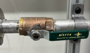
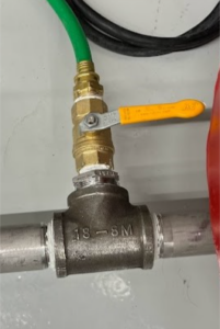
The right pane shows a ball valve in the CLOSED position.
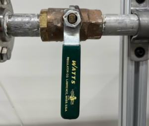
The left pane shows a ball valve in the OPEN position.
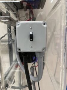
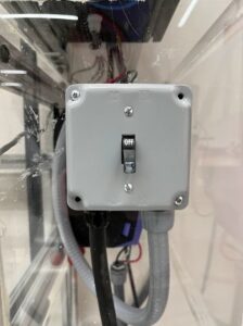
- Flip switch on the right-hand side of the FFB to the ‘on’ position
- Select the desired pump power using the PAC Display Runtime Pro System.
- Turn the power to the pump on.
- Record data.
- Pump power can be changed with the pump running and does not require turning off the pump.
- Note that for some pipes the pressure drop will not register with the pressure transducers at low flow. The Rosemount 0-200 inches of water pressure transducer will display –1.24 or –1.25 in the event of extremely low flow. Simply increase the flow rate until nonnegative numbers are displayed.
Shutdown:
- Turn off the pump.
- Flip switch on the right-hand side of the FFB to the ‘off’ position
- Open all ball valves with respect to the pipe sections.
- Under the direction of the lab manager, water may be left in the tank, or it will need to be drained. Always consult with the lab manager in making this decision, to conserve water and preserve the FFB.
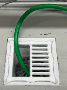
- If the lab manager gives the OK for draining the tank, ensure that the hose is well inside the drain. Open the drain valve and allow all water to drain from the FFB. Draining water from the tank will also Drain the FFB.
- The left picture is the drain valve, the right picture is the hose securely in the drain.
Viewing and Saving Data:
- When data collection has finished, open the LFB Data folder, located on the desktop of the computer.
- Find the data file that contains the current date and time.
- Rename the file to your liking.
- After approximately 5 seconds, a new file should pop up again, assuming the data collection software is still running.
- Copy the file to a USB Drive and open it on your computer.
- The data is saved as a ‘.hoo’ format and will need to be saved as a CSV for future use.
Pipe Changing:
The FFB is equipped to easily switch out pipes. To do so, please follow the steps to ensure safety.
CHANGING PIPES ON THE FFB IS A TWO PERSON JOB. DO NOT ATTEMPT TO DO IT ALONE.
Removing Pipe Sections
- Ensure that the power to the pump is turned off.
- Ensure that all valves are open on the FFB.
- Open the drain valve and allow all water to exit the FFB.
- Note that some water may remain in the FFB even after draining. Have a bucket on hand in case of accidental spills.
- With the tank drained, close the valves associated with the section of pipe you wish to change.
- Disconnect the plastic tubing that connects to the pipe, by pushing on the orange collar, while simultaneously pulling the tube from the collar (see below). Be aware of small spills at this point.
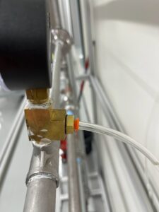
- Place the tubing near the pipe. Make sure to label any tubing, to not confuse which location it corresponds to.
- Using two wrenches, remove the flange bolts on one end of the pipe. Have the second person hold the now unattached pipe end.
- On the other end of the pipe, remove the flange bolts on the other end of the pipe.
- At this point, the pipe should pull freely from the FFB.
- Slide the pipe out of the FFB frame, taking care not to catch the flanges on the frame rack or on any tubing.
Installing Pipe Sections
- Slide the new desired pipe into the FFB. Take note that the flow is from left to right. The pressure gauges should face outwards into the room, with the left pressure gauge having a two-foot section of pipe in front of it.
- With the pipe in the desired location, place a gasket between each flange, such that the holes in the gasket line up with the holes in the flanges.
- Thread the flange bolts through the flange, and lightly tighten the nuts until finger tight.
- With a wrench, fasten the bolts evenly, rotating between the 4 bolts, until all bolts are sufficiently tight.
- Reconnect the tubing to the pressure gauges, by pushing the tubing into the orange collar. Pull lightly on the tubing to ensure that the tubing is installed correctly.
The FFB will need to be bled of all air at this point.
- Open all valves in the FFB and set pump power to 100%. Turn on the pump.
- Disconnect the male end of the quick connect from the pressure transducer. Lightly pressing the tip of the quick connect will allow water and air to exit the FFB. Using a cup, drain tubing until all air is evacuated from the tubing. Repeat with all other pipe sections.
- ALL AIR NEEDS TO BE BLED FROM THE FFB FOR ACCURATE DATA.
- Turn off the pump and close all valves with respect to the pipe lengths.