UOL Spray Dryer SOP
Standard Operating Procedure
Introduction:
The spray dryer (Figure 1) is located in the Unit Operations Laboratory (MEB 3969). Spray dryers are used to form dry powder from a liquid or slurry by rapidly drying with hot gas. This spray dryer uses a spray nozzle to disperse the liquid or slurry into a spray with a controlled drop size.
Before operating the Bowen Spray Dryer, familiarize yourself with the plumbing, display gauges, control panel, pump, pump drive, and blower. The Bowen Engineering Spray Dryer is a pilot-scale device commonly used for drying thermally sensitive materials. In the Senior Lab (MEB 3969), it has been used for drying a variety of solutions including soap, salt, and beer. Before using this Spray Dryer, verify that any solution pumped through the system will not clog the lines or the spray nozzle. Check with the lab manager before preparing a new solution.
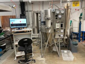
Figure 1. Spray Dryer.
Health & Safety Warnings:
- Safety glasses must be worn when operating this equipment.
- The manual gas control valve must be closed after each run.
- Do not remove the drive shaft guard.
- To prevent overheating, the gas burner will not light until the blower is powered on.
- Use caution when opening the spray dryer door during operation since liquid may escape from the drying chamber.
- Caution – exterior surfaces may be hot!
- Rotating equipment hazard: Use caution when near the pump.
Procedures:
Pre-Run Steps
- Mix feed solution in tank(s) located behind the spray dryer (refer to Figure 2). Verify that the feed tank valves remain closed until you are ready to run.
- Set (open) valves on feed tanks to feedstock solution to pump as desired (refer to Figure 2).
- This step will be done by lab personnel: Using a wrench, remove the pump drain plug until feedstock/water flows out of the pump housing. Then, replace the plug, tighten it finger tight, and then tighten it ¼ turn with a wrench (Figure 3 shows the pump).
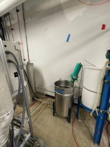
Figure 2. Mixing tank. In the left background is a larger tank used for very extended runs. When ready to run adjust the valves seen leaving the tank to valve off the other tank and to connect to the spray dryer.
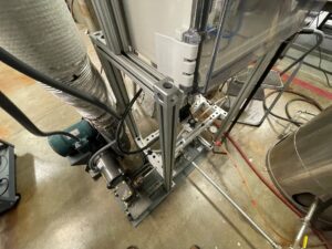
Figure 3. View of the pump.
- Using a small crescent wrench, open the main gas pipe valve ½ turn so that the valve headpiece is in line with the pipe. The valve is located on the rear of the spray dryer (refer to Figure 4).
- Open the compressed air valve located on the right side of the dryer. (refer to Figure 5).
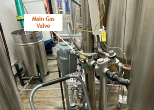
Figure 4. The valve for the gas line is seen immediately in front of the gray-colored gas meter. 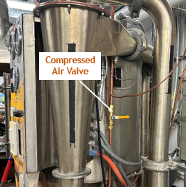
Figure 5. Main air supply valve in closed position. - Verify that the air pressure regulation to 30 psi. The air pressure regulator is located on the lower front panel. If the pressure regulator is not at 30 psi contact lab personel.
- Turn on the main power switch located on the upper left of the control panel.
Check the Chamber
- Open the chamber door. The chamber’s light switch is located on the right side of the control panel. Verify that there are no obstructions in the chamber. If the chamber requires cleaning, use the hose located behind the spray dryer to clean the system. Cleaning supplies are in the stock room. It is your responsibility to clean the spray dryer after each use.
- Verify that the spray nozzle (Figure 6) is connected to the air and feed lines.
- Close the chamber door.
- Latch both chamber door fasteners to secure the door.
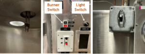
Figure 6. Spray nozzle and chamber light (left-hand image). The light on-off switch is shown in the middle image. See also the burner on/off switch. The right-hand image shows the main power on-off switch
Set Pump Speed:
- Open the valve at the base of the desired liquid tank to allow flow into the pump.
- To turn on the pump, press the red button labeled “Pump Switch” on the Opto interface.
- Once the pump has started you can adjust the power of the pump by changing the Pump Power percentage through the Opto interface.
- The flow rate of the pump should be displayed just below the pump power.
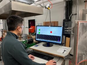
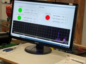
Figure 7. The pump is controlled by Opto 22 equipment. You will control the pump from the GUI.
Set the Air Speed
- To turn on the air, press the red button labeled “Compressed Air Switch” on the Opto interface.
- Once the air has started you can adjust the flow rate of the air by changing the Gas Glow Setpoint through the Opto interface.
- The flow rate of the air should be displayed just below the Setpoint.
- Confirm that the spray is adequate before closing the chamber door (Refer to Figure 8).
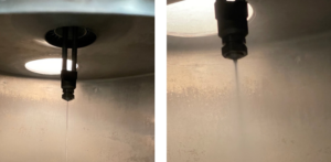
Figure 8. While the pump is on, you can verify that there is a stream of fluid (left image). While the pump and the air are on, you can confirm that the spray is appropriate and that there are no obvious issues with the nozzle (right image).
Starting the Blower
To start the blower, press the red button labeled “Blower Switch” on the Opto interface.
Lighting the Burner
Note – the blower must be running to ignite the burner (Figure 9).
- Verify that the main gas valve is open.
- Push the black start button (burner control – see Figure 6) located directly above the fan start/stop control on the spray dryer control panel. Verify that the burner is lit via the observation port (Figure 10) on the burner assembly.
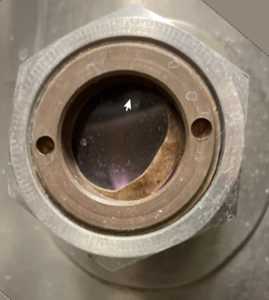
Figure 10. Burner observation port.
Sample Collection
- Sample material is collected in the bell jar located at the bottom right of the spray dryer. The jars will thread in below the cyclone separator (Figure 11).
- Additional bell jars and spray nozzles are in the cabinet adjacent to the spray dryer.
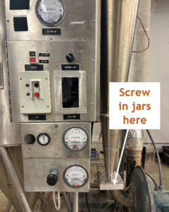
Figure 11. Collection jars thread in below the tapered cyclonic separator.
Shutdown:
- Turn of the burner by pressing the stop button on the spray dryer control panel.
- Turn off the blower using the Opto interface.
- Set the air speed to Zero. Stop the air.
- Set the pump speed to Zero. Stop the pump.
- Close the main gas valve.
- Fill one of the liquid tanks with pure tap water. Close the valve to your sample tank and open the valve to the new pure tap water tank.
- Turn the pump back on and run clean water through the system for 10 minutes.
- Set the pump speed to Zero. Stop the pump.
- Turn off the main power switch.
- Close the feed valves (ball valves) that control the feed flow from the feed tanks to the pump.
- Drain and rinse the feed tanks as needed.
- Determine the moisture content of the sample that you have acquired. This will mean you will need to have tared the sample jar.
- Rinse the spray dryer chamber with tap water.
- Clean the work area.
- If you plan on leaving feed solution in the tanks overnight, it must be labeled.