UOL Ultrafiltration and Reverse Osmosis SOP
Standard Operating Procedure
1. Introduction
Ultrafiltration and reverse osmosis are filtration processes for the removal of a solvent selectively relative to a solute by pressure-driven flow across a solute-rejecting membrane. Ultrafiltration deals with macromolecular solutes and reverse osmosis with small solutes. This apparatus, in the Unit Operations Laboratory, can demonstrate either ultrafiltration or reverse osmosis.
An ultrafiltration filter membrane has larger pores than a reverse osmosis membrane. Ultrafiltration only removes particulates and solids, but it does so on a microscopic level; the membrane pore size is on the order of 0.02 microns. Ultrafiltration is pressure-driven membrane filtration that selectively retains species in aqueous solutions based on their size, charge, and composition. Water is forced through a membrane, which typically has a pore size of 0.002 to 0.1 microns (Seader et al suggest 0.001 to 0.02 mm)
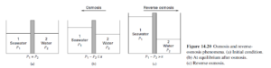
Osmosis refers to the passage of a solvent, such as water, through a membrane that is much more permeable to solvent (A) than to solute(s) (B) (e.g., inorganic ions) (see Figure 1, from Seader et al., 2011). As a separation process, osmosis leads to mixing rather than separation. The direction of transport can be reversed (reverse osmosis) when a supplemental pressure is applied so that P1 – P2 > p, partially removing solvent from a solute-solvent mixture. p is the osmotic pressure. Recall that only a portion of the solvent is transferred to the permeate (the rest being retentate).
A reverse osmosis system, on the other hand, uses a semipermeable membrane that has a much smaller pore size 0.0001 micron), blocking most total dissolved solids and allowing only the smallest water particles to pass through.
 \
\
Figure 1. Osmosis and reverse osmosis (a) initial condition (b) equilibrium after osmosis and (c) reverse osmosis.[1]
[1] Seader, J.D., Henley, E.J., and Roper, D. K. 2011. Separation Process Principles – Chemical and Biochemical Operations, Third Edition, John Wiley & Sons, Inc.
2. Safety:
- Safety Glasses Must Be Worn at All Times When Operating This Equipment. Hoses may become dislodged and spray process fluid on operators and nearby equipment. It is advisable to wear a lab coat when operating this equipment.
- Never Leave This Equipment Operating Unattended. This equipment may malfunction, resulting in flooding or equipment damage.
- Do Not Place Any Items on the Equipment Surface. Items placed on the surface of this equipment can vibrate into the feed chamber and become lodged in the pump causing severe pump damage.
- This Equipment Uses High-Pressure Water and High Voltage. Understand the different pressures and equipment requirements associated with ultrafiltration and reverse osmosis filtration. Use of inappropriate fittings may result in severe injury or death.
- Trip Hazards.
- Never operate the pump without liquid in the tank!
- Never make a sudden change in the pump speed. Always adjust the pump speed gradually.
- Always check the hose connections before operating the pump.
- Be aware of the hoses and electrical cords located behind the equipment.
- Verify that the appropriate pressure gauges are installed for your process. Reverse osmosis requires high-pressure gauges. Ultrafiltration requires low-pressure gauges.
- High Pressure Equipment. The output line from the system pump is fitted with a pressure relief valve. Consult with the lab manager regarding pressure release settings for this valve. Do not adjust the pressure relief valve.
- Use only carbon-filtered water from the filtration system located behind and to the right of the equipment. Do NOT use DI (de-ionized) water or tap water. The carbon filter dispensing system and feed valves to the dispensing system are shown in Figure 2.
2.1 SAFETY WARNING – Reverse Osmosis Clamps
All the clamps from the tank outlet to the feed pump inlet can be low-pressure style (since it is not high pressure until after the discharge of the pump). The 3/4″ clamps with the hinge are rated above 2000 psi at 70°F. The 1.5″ clamps on the pressure gauges and the 3″ clamps on the 2540 Spiral housing require the dual bolt high-pressure clamp (Figure 2).
The high-pressure bolted clamp is suitable for any Tri-clamp application. It must be used in any lines and connections in the high-pressure piping circuits of the reverse osmosis system. For those lines in the high-pressure circuit, do not use any other type of clamp! These high-pressure clamps are properly tightened when the two halves of the clamp are butted together.
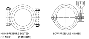
Figure 2. High-pressure clamp (left) and low-pressure (right).
The low-pressure hinged clamp is suitable for low-pressure applications. Do not use these types of clamps in high-pressure circuits.
2.2 Pump Safety Notice
It is unsafe to operate a centrifugal pump when both the suction and discharge ports are closed off by valves at the same time. This will destroy the pump!! When a pump operates with closed valves, nearly all the motor power output is converted to heat and the temperature of the trapped liquid will continue to rise. As it does, the liquid will expand, and additional pressure will be created as the liquid expands and the temperature increases eventually to above the liquid boiling point. These pressures will exceed the design pressures of the pump, likely causing irreparable damage.
2.3 Storage and Disposal of Waste
All waste materials must be stored in sealed Nalgene waste containers. The containers must be clearly labeled “Unwanted Material” with the contents of each chemical component in mol % or volume % concentration written clearly on the container. The container must also be labeled with the group/experiment name and the date. The labeled and sealed container must be placed in the waste collection area located in the southeast corner of the senior lab.
Any chemicals or materials that require temporary storage until the next lab period must also be labeled with the contents of each chemical component in mol % or volume % concentration written clearly on the container. Be sure to include the name of your group and the date, do not label temporary storage containers as waste. Contact the lab manager if you are uncertain as to where to store your samples.
If the material to be temporarily stored is flammable it MUST be stored in the flammables cabinets located on the east wall of the senior lab. If the chemicals are not flammable and not hazardous they may be stored in sealed containers next to the ultrafiltration equipment. These containers must be properly labeled as described in the previous paragraph. Check with the lab manager before deciding on the procedure for temporary storage of chemicals.
3. Equipment Description
Figure 3 shows the equipment, with labels. Note, that there is a component for ultrafiltration and a component for reverse osmosis.
For ultrafiltration, the basic system incorporates the plate and frame Lab Module M20 with 7.8 ft2 (0.72 m2) of membrane area. The Lab Module M20 accepts all types of flat sheet polymeric membranes. It has the unique feature of being able to simultaneously screen several flat sheet membranes. The Lab Module M20 can accept as few as 4 flat sheets to as many as 40 sheets. This flexibility allows the module to run anywhere from 1 to 8 gallons per hour.
For reverse osmosis, a spiral membrane pressure vessel, 2.5-inch diameter by 40-inch length, is included for testing spiral elements at both low and high pressure. A ceramic membrane module for testing laboratory-scale ceramic MF or UF elements is included as well.
- Butterfly clamp
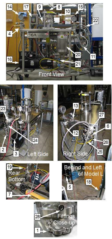
- Ceramic Filter Module
- Feed line
- Heat exchanger
- Pump Outlet
- High pressure clamp
- Hydraulic jack for Labstack
- M20 Labstack Module
- M20 Labstack Module-feed inlet
- M20 Labstack Module-retentate outlet
- Permeate line
- Retentate pressure control valve
- Clamp
- Pressure gauge-retentate
- Pressure gauge
- Pump (positive displacement)
- Pump-controller
- Pump-power cord and outlet
- Pump-pressure relief valve
- Reservoir
- Reservoir-drain valve
- Retentate line R.O. (Spiral Membrane)
- RO-vessel
- Input to RO
- Hydraulic line
- RO-retentate outlet
- Fitting O-Ring
- Fitting O-ring
Figure 3. Apparatus components.
Figures 4 and 5 show filters. Figure 6 is a schematic of the apparatus.
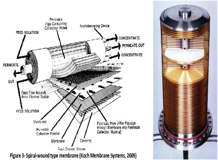
Figure 4. Flat sheet type membrane assembly (ultrafiltration) in plate-and-frame module shown on the right. Spiral membrane (reverse osmosis) is shown on the left.
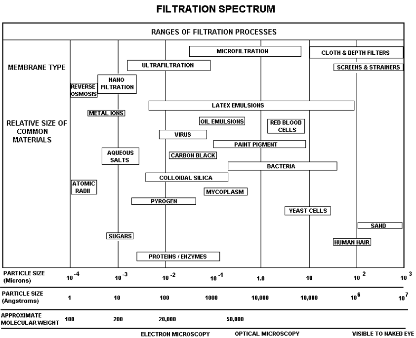
Figure 5. The spectrum of required filters. This shows the difference between ultrafiltration membranes and reverse osmosis membranes.
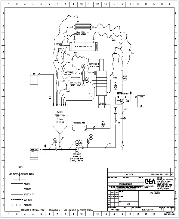
Figure 6. Schematic of apparatus.
3.1 Pressure Measurement
The pressure gauges – monitoring pressure – are important for this apparatus. Pressure will be high.
- The top two pressure gauges measure the pressure on the feed/concentrate side of the membrane (Items 14 and 15 in Figure 3). The permeate pressure should be atmospheric, as the permeate hose goes directly to the drain.
- The two gauges measure the pressure loss due to flow from the inlet to the outlet of the element.
3.1 R.O. Membrane Specifications
Listed below in Figure 7, are the specifications for a reverse osmosis membrane. These are the membranes that are typically used with the GEA Model L system. Consult the lab manager for information on other membranes.
Note:
- Chlorine will damage membranes – Do not use tap water or D.I water
- Use the carbon filter water system located behind the filtration system.
- Consult with the lab manager regarding water system operation.
3.2 Ultrafiltration Membrane Specifications
Figure 8 provides specifications for an ultrafiltration flat sheet membrane.
4. Startup Checklist
- Remove all items from the top of the equipment.
- Verify that all clamps are secure.
- Verify that the concentrate/retentate (item 22 in Figure 3) and permeate (item 11 in Figure 3) hoses are both secure inside of the feed tank. These hoses can easily slide out of the feed tank and flood the work area.
- Verify that the correct membrane is installed or install a membrane as required.
- Consult with the lab manager for instructions on membrane installation.
- Verify that the feed tank drain valve is closed.
- Connect system power – the unit does not have an on/off switch, connecting the power cord applies power to the system.
- Ensure that the pump speed is set to zero (“0”).
- When the forward button is pushed on the pump control panel the pump will start at the setting it was last operated at. Be prepared to quickly stop the pump if it should start at a high speed. Verify that the pump control unit is set to zero. The control is shown in Figure 9.
- Verify that the feed tank wire mesh is in place at the bottom of the tank.
- Fill the tank with carbon-filtered water – NOT tap or DI water or your feed solution.
- Mix feed solution as required – use carbon-filtered water – NOT tap or DI water.
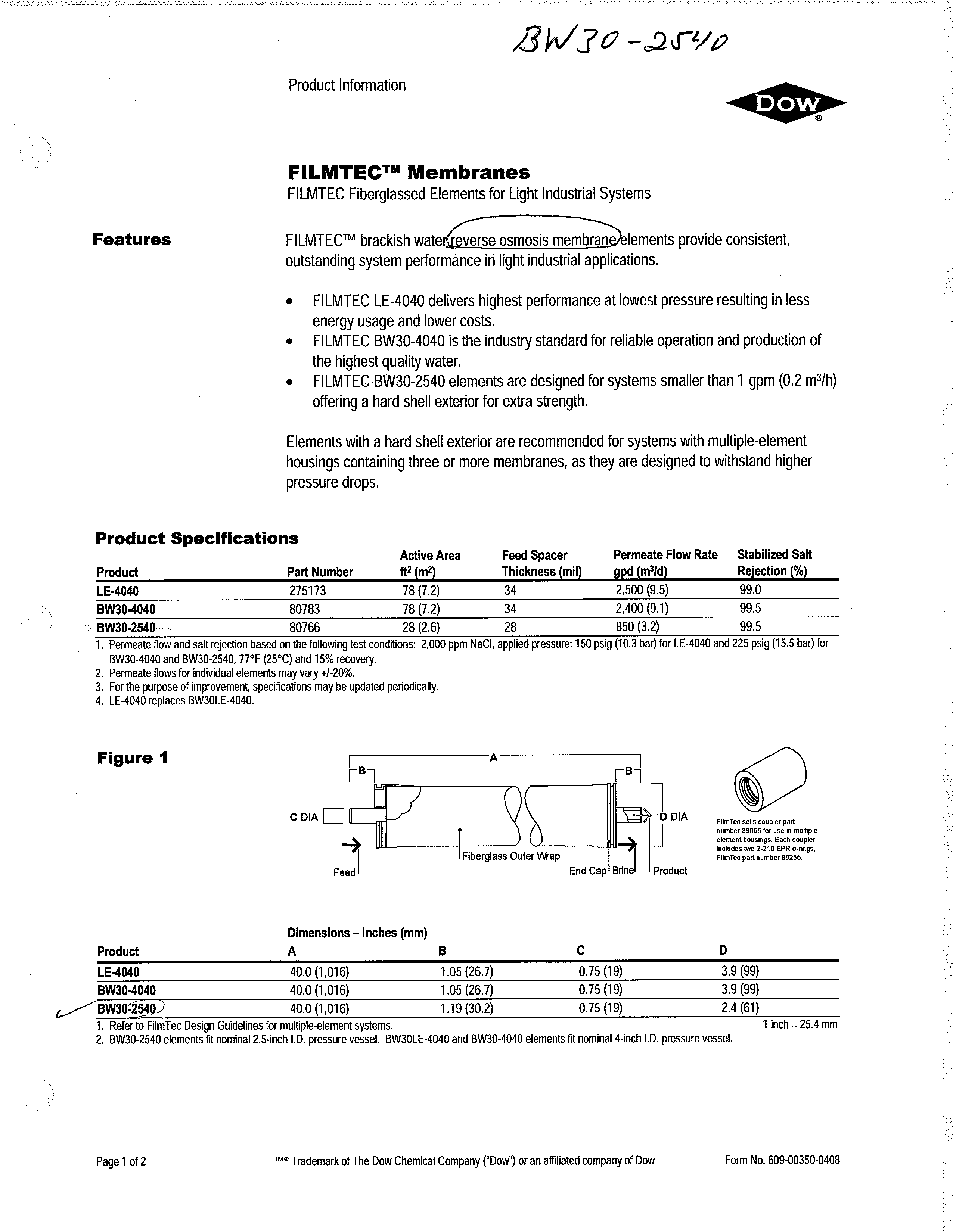
Figure 7a. Membrane specifications. See Figure 7b for additional details.
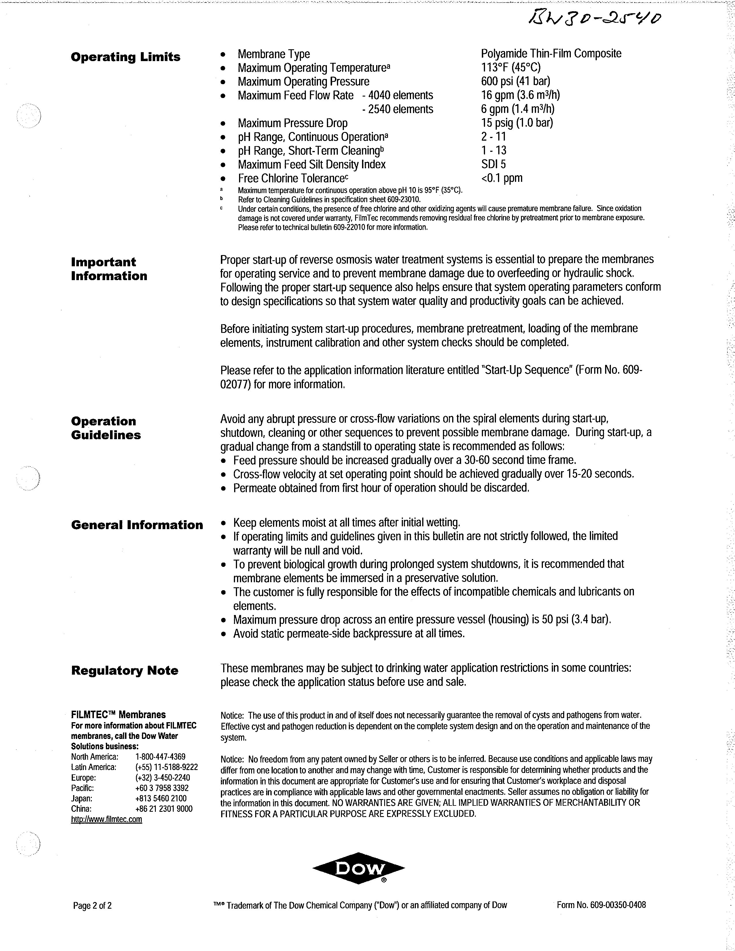
Figure 7b. Membrane detail. See Figure 7a for specifications.
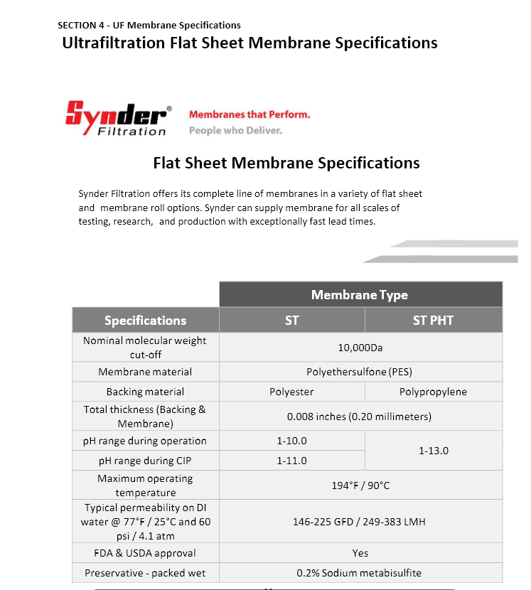
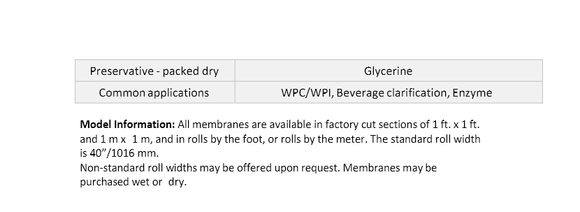
Figure 8. Specifications for an ultrafiltration membrane.
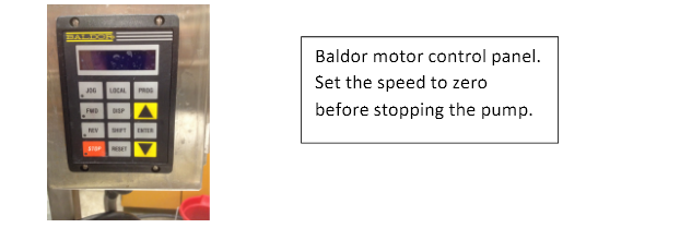
Figure 9. Pump control.
5. Reverse Osmosis (R.O.) Separation
Consult with the lab manager before proceeding with this section. The lab manager will install the R.O. membrane before you begin your experiment.
- Plan on operating the system with water first to verify operation.
- Once you have established that the system is operating correctly and there are no leaks, drain the feed tank and then fill the feed tank with your process fluid.
- Verify with the lab manager that the correct R.O. filter, high-pressure clamps, and appropriate plumbing are installed.
- Fill the feed tank with carbon-filtered water or process fluid (sodium chloride and filtered water etc.).
- Turn on the pump by pressing “FWD” on the pump controller.
- The motor control displays the motor speed in Hz (Hertz).
- Push the increment (up arrow) button on the Baldor control module until the display reads 2 Hz. It is important to break in a new membrane by slowly increasing the flow/pressure over about 20 minutes.
- Run the pump at a very low setting, between 2 – 8 Hz, for approximately 2 minutes. The pump may time out when operated between 2-6 Hz. If it does time out, stop the pump, set the speed to zero, and then push the forward button and slowly bring the pump up to the desired speed
- Do not make sudden changes in flow or pressure during operation. This may permanently damage the membrane.
- Gradually increase the pump speed to (12 – 16 Hz) by pressing the up arrow on the controller.
- When stopping the pump, gradually reduce the speed to zero and then press the stop button. Remember that the pump will start at the last speed setting used. Consequently, you must always reduce the speed to zero before stopping the pump.
- Allow the system to stabilize at a low flow rate and pressure for approximately 15 minutes if you are using a new membrane. If you are using a membrane that has already been broken in you may skip this step and proceed to run the system – taking care to stay within the membrane’s operating pressure and flow ratings.
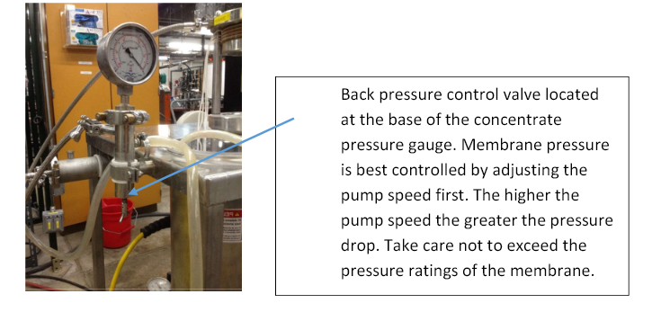
- Pressure across the R.O. membrane is primarily controlled by the pump speed. Back pressure may be increased by adjusting the back pressure control valve located at the base of the concentrate pressure gauge on the right side of the apparatus. To adjust the back pressure slowly begin to close the concentrate back pressure control valve while carefully monitoring the pressure and flow readings. Figure 10 shows the back pressure control valve.
Figure 10. Back pressure control valve.
6. Ultrafiltration Separation
Consult with the lab manager before proceeding with this section. Ultrafiltration typically operates at 70-120 psi. The pressure is a function of the membrane type and the material being filtered. The typical pH and temperature range for a PES (polyether sulfone) type ultrafiltration membrane is 2-10 pH and 55°C. Review the datasheet for the membrane you are using before operating the equipment.
The Labstack 20 is a plate and frame cross-flow membrane filtering system. It is comprised of multiple spacer plates, locking rings, and support plates. The flat sheet membranes are assembled on the stack plates. The frame is comprised of the two horizontal flanges in the center of the tabletop, supported by the two metal posts. The top flange is referred to as the upper flange while the lower flange is referred to as the moving flange. The jack to the Labstack is located under the tabletop in the back of the cart. The assembly method is given below.
- Check with the lab manager to verify that the system is clean and ready for use.
- Check all connections in the tubing, and make sure everything is connected properly.
- Remove and clean the old stack assembly.
- If a stack is in place, release the pressure on the stack by opening the stack pressure isolation valve which is in line with the pump and stack, and then open the pressure release valve on the stack compression pump. This black handle is located on the side of the jack that is toward the pump, away from the operator. Once the bottom stack flange has been lowered, remove the plate/filter assembly.
- Remove the old filters from the stack and gently clean the support and spacer plates as instructed by the lab manager.
- Remove the upper and lower O-rings from the two flanges. Gently wipe the O-rings with a Chem-Wipe and then apply a thin layer of vacuum grease to the upper and lower O-rings before placing them back into the upper and lower grooves on the flanges. You may need to reinsert the upper O-ring when you complete the stack assembly.
- Assemble a new filtration stack. Consult with the lab manager to review stack assembly procedures before beginning. If you assemble the stack incorrectly you could damage the membrane.
- Place a damp towel, cloth, or paper towels on a clean table. Moisten a support plate with carbon-filtered water and place it on the towel (side facing up is arbitrary). Support plates have a metal nib protruding from the side (Figures 11 through 15).
- Now, remove a single flat sheet membrane and use the membrane template to cut out circular flat sheets to fit over the support plate. Use a sharp box cutter to cut the membrane material. Try to cut as exactly as possible in the inner circle of the template. Extra space on the outer edge is acceptable (Figure 12).
- Re-wet the support plate and then place and center the newly cut membrane on the wetted support plate SMOOTH SIDE UP, FACING YOU, and then position a lock ring in the center hole.
- Make sure that the membrane stays wet throughout the entire process. If a membrane dries up, it is unusable.
- Carefully turn the support plate over so that the membrane/lock ring assembly faces the table and place another cut-out (repeat the previous step) membrane and lock ring on the other side of the plate. Be sure the smooth side of the membrane is facing up toward you. The smooth side of the membrane should be on the outside of both sides of the support plate.
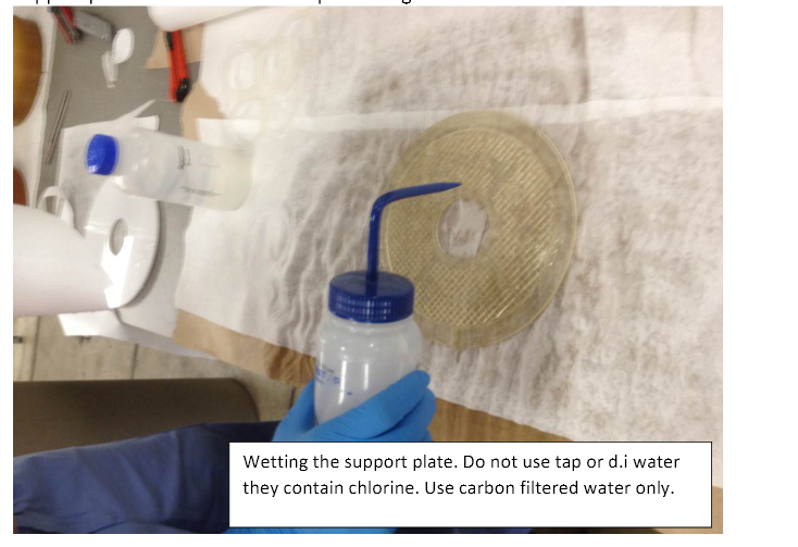
Figure 11. Wetting the support plate with carbon-filtered water.
Figure 12. Support plate with the permeate outlet port.
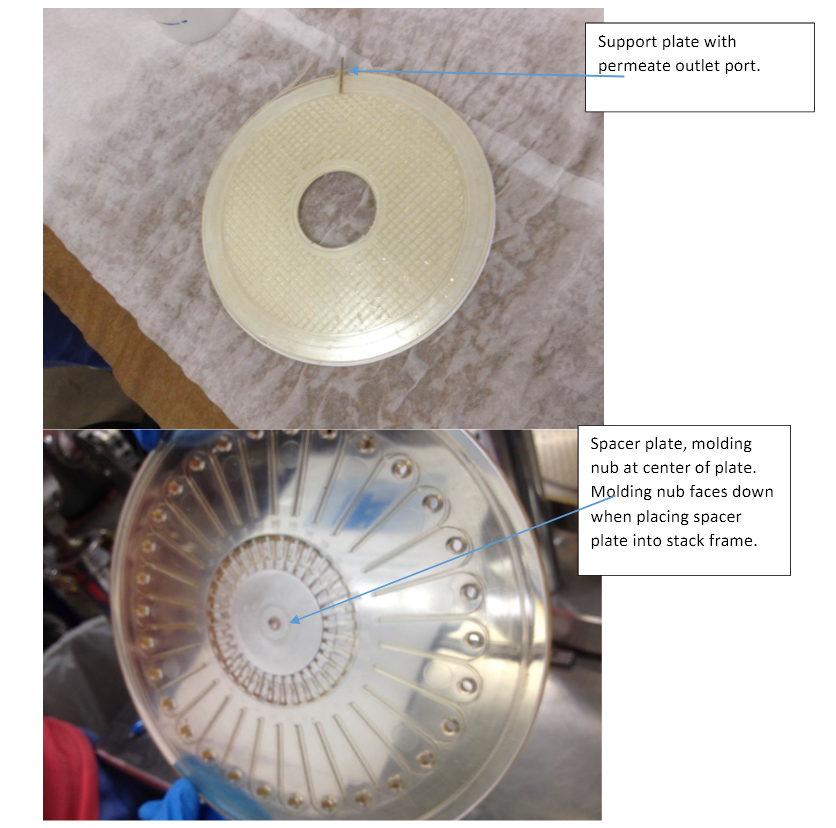
Figure 13. Spacer plate with nub.
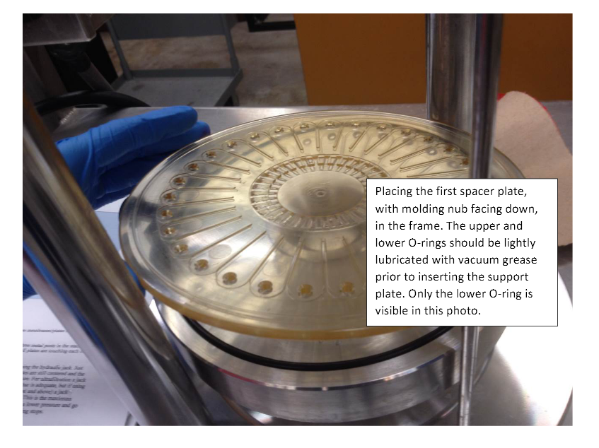
Figure 14. Assembly with o-rings.
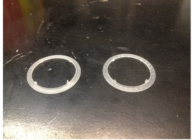
Figure 15.
-
- Interlock the two lock rings via the pins and holes in the lock ring. There should now be a membrane and lock ring on each side for a total of two membranes and two mating lock rings per support plate.
- Now place the support plate membrane assembly on top of the spacer plate. Then, place another spacer plate with the molding nub (see Figure 14) and ribs facing DOWN, on top of the support plate/membrane assembly. Repeat the previous steps until the desired number of membrane/plate assemblies is reached. Always end the top of the stack with a spacer plate. Be sure to keep the membranes and plates moist while you are assembling the stack.
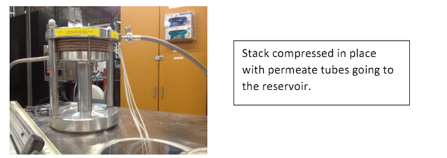
Figure 16. Stack compressed in place.
6.Place the new stack in the plate and frame and compress the stack. The permeate tubes that connect to the support plate need to be facing the reservoir. Once everything is in place, slowly start to jack up the stack using the hydraulic jack. Just before the stack touches the upper flange make sure that all plates are still centered, and the O-ring is still in place in the top flange.
-
- Verify that the pressure isolation/release valve is open and the pump release valve
is closed. - Slowly actuate the stack compression pump. This will cause the lower flange to move upward, compressing the stack.
- The stack is sufficiently compressed when the pressure reading on the hand pump reads 180 bar. Do not exceed 200 bar
- Verify that the pressure isolation/release valve is open and the pump release valve
Once you have compressed the stack, close the stack pressure isolation valve that is in line with the pump and stack (Figure 17).
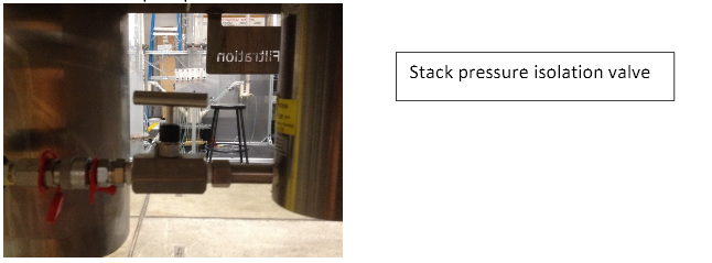
Figure 17. Stack pressure isolation valve.
7. Connect a filtrate tube to each of the stack filtrate outlet ports. Place the other end of the filtrate tube in the feed tank or a sample container, as desired. Once the system is running you may take samples from each stack using these filtrate tubes.
8. Fill the tank with carbon-filtered water.
9. Plug the system’s power cord into the outlet located behind the filtration equipment. The control panel should now be turned on. When the forward button is pushed on the pump control panel, the pump will start at the setting it was last operated at. Be prepared to quickly stop the pump if it should start at a high speed. Verify that the pump control unit is set to zero.
10. Always adjust the pump speed gradually. Never jump from very slow to very fast or vice versa.
11. When stopping the pump, gradually reduce the speed to zero and then press the stop button. Remember that the pump will start at the last speed setting used. You must always reduce the speed to zero before stopping the pump.
12. Flush the new membrane stack with water.
13. Controlling the pump speed.
-
- Push the FWD button and then push the yellow increment/decrement arrow buttons to control the speed. Do not make sudden changes in speed! The pump may shut down when operated at low speeds in the range of 2-3. If it does, press the stop button and then restart the pump.
14. Start the pump at a low speed (setting of 2) and run at the low setting for about 3 minutes. Then, increase the speed to 3-5 and run for 10 minutes. Now increase the speed to 5-10 and run the system for another 10 minutes. Constantly monitor the pressure gauges during this process. Take care not to exceed the pressure rating of the membrane.
15. Drain the water by pumping the water into a secondary container or drain the feed tank using the valve at the base of the tank. Take care not to operate the pump without liquid in the tank.
16. Prepare the feedstock and place it in the feed tank or feed vessels.
17. Review the operating parameters for your membrane and feedstock.
18. Start the pump and begin the separation process. Always start at a speed of 2 and run for about 2 minutes and then gradually increase the speed while monitoring the pressure and checking for leaks in the system.
19. Adjusting system backpressure:
-
- As you gradually increase the pump speed you should see flow out of the filtrate tubes as well as through the retentate tube. The retentate and permeate flows may be adjusted by adjusting the system back pressure. To do this slowly, close the backpressure valve while monitoring the pressure drop as displayed on the gauges.
20. Take samples as required.
21. Analyze samples as required.
22. Shut down the equipment and store samples and feedstock as directed by the lab manager.
7. System Shutdown
At the end of each run, you must decide whether to store your sample solution or discard it. If you elect to store your solution, please store it in the appropriate containers and make sure to label the containers correctly. Consult with the lab manager to determine the best location to store your solution. If you decide to dispose of your solution, consult with the lab manager to determine the proper procedure for disposal.
The shutdown procedures are as follows (the numbers below refer to the nomenclature in Figure 3).
- Open pressure control valve [12].
- Press the “STOP” button on the control panel to turn off the system pump.
- Pump your solution into storage or disposal containers or drain the system solution into the appropriate container from the feed tank drain valve [21].
- Close the reservoir drain valve.
- Fill the reservoir with carbon-filtered water from the R.O. water supply system.
- Turn on the pump by pressing “FWD” on the pump controller.
- Slowly adjust the pump speed to the desired flow, using the up and down arrows on the controller.
- Slowly close the pressure control valve to build up system pressure. Stop increasing the pressure once fluid begins to flow through the permeate line [11].
- Allow the water to circulate for several minutes.
- Open the pressure control valve.
- Press the “STOP” button on the control panel to turn off the system pump.
- Open the reservoir drain valve to flush the water out of the system.
- Close the reservoir drain valve.
- Unplug the pump power cord [18].
- Close the main building water supply valve (ball valve) – this is the YELLOW ball valve that feeds the charcoal-filtered R.O. water system.
- Verify that the membrane has been cleaned and stored in the proper solution – see membrane documentation – consult with the lab manager about this step.
- Verify that your solution is stored as required. Follow chemical/waste storage procedures as outlined in the laboratory safety procedure.