UOL Bioreactor SOP
Standard Operating Procedure
1. Introduction
This describes the basic operating procedures for the bioreactor that is located in the Unit Operations Laboratory. The Eppendorf Bioflo 120 is a bench-scale bioreactor/fermenter system capable of microbial fermentation as well as mammalian cell culture applications. All users/operators must meet with the lab manager for equipment-specific training before operating this equipment. The apparatus is shown in Figure 1. A generic bioreactor is shown in Figure 2.
Do not proceed with testing without familiarizing yourself with and following all safety procedures. A basic list of safety considerations is provided in Section II of this SOP.
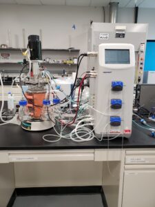
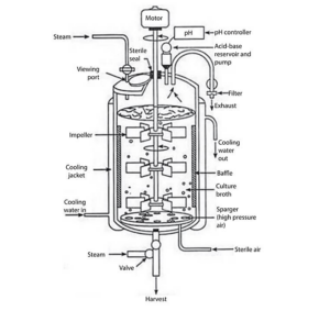
| Figure 1. Bioreactor, located in the Senior Laboratory. | Figure 2. Generic bioreactor – schematic only, to demonstrate generic components (after Kuila, A., & Sharma, V. (2018). Principles and applications of fermentation technology. John Wiley & Sons, Inc. |
2. Safety
Specific safety hazards include, but are not limited to, electricity and water, compressed gas cylinders, and chemical hazards. The operator/user must provide a Safety Data Sheet for each chemical and cell type used with this equipment. Safety glasses are required at a minimum, depending on what experiment is being carried out.
3. Equipment Description
Additional photographs are provided in Figure 3. This collage shows the water cooling valve, the air regulator, and the compressed gas cylinder. Only the laboratory manager should adjust the regulator.
The Eppendorf[1] controller allows control of the following reactor parameters: temperature, pH, DO (dissolved oxygen), agitation speed, and gas /air control.
[1] Manufacturer of the bioreactor.
Some other features of the apparatus are:
- The working volume of the reactor vessel is between 0.8 and 2.2 liters.
- The reactor vessel is heated using an electric heating blanket which is attached to the outside of the reactor vessel with Velcro straps. The reactor vessel is cooled by flowing water through the outer reactor jacket. The cooling water drains into the sink located to the left of the reactor.
- Before operating the reactor, verify that the cooling water drain tubing (this is the reinforced ½ inch O.D. tubing with a metal “U” shaped clamp at the end) is placed in the sink near the drain.
- Check with the lab manager and assess if the following bullets apply to your experiments.
- Do not use hydrochloric acid as it will degrade the stainless steel.
- Sulfuric acid and sodium hydroxide are the recommended acids and bases. Use an anti-foaming agent to limit foaming/overflow in the reactor.
- Consult your instructor or the lab manager for guidance on mixing the antifoamer. Antifoam –C or Antifoam-SE are typically used. The antifoamer is usually diluted in D.I. water. See the attached document for more details regarding the types of antifoam. The antifoaming solution is pumped into the reactor when the level of foam in the reactor reaches the height of the antifoam detection probe. Once the level of foam is reduced such that it is no longer in contact with the foam, the antifoam pump will shut off.
4. Procedures
A brief description of each control parameter is provided below. For a more detailed discussion of reactor operation please consult the operator’s manual.

Figure 3. Photographs of various valves and regulating components for cooling and for air/gas supply.
4.1 Calibrating the Dissolved Oxygen (DO) Probe
Figure 4 shows the controller screen that will allow calibration of the polarographic DO[2] probe. The controller is always on. Figure 4 designates various functions that are described immediately below.
[2] A polarographic sensor operates by inducing an electrochemical reaction with the dissolved oxygen; the resulting electrical signal indicates the DO concentration.
4.2 Setting the Electronic Zero
- In the System Setup screen, ensure that DO is selected for Sensor 2 (2-DO on the screen), and save any changes that you are prompted for.
- Disconnect the DO sensor from the cable or control station.
- Navigate to the Calibration screen and select 2-DO from the Loops
- Allow the DO PV(process variable) measurement to stabilize.
- Touch the Set Zero edit box (Figure 4) and then use the onscreen touchpad to enter 0. Then touch the check mark button to confirm.
- Reconnect the DO sensor to the cable or control station.
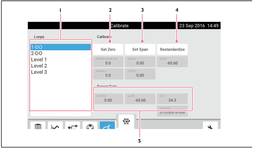
Figure 4. ISM[3] Polarographic DO Calibration screen. The numbers designate functions or readouts. “1” shows the Loops field. “2” lets you set the zero. “3” is for setting the span. “4” is the restandardize procedure and “5” shows the data that your sensor is recording.
[3] Intelligent Sensor Management is a trademark of Mettler. It is a digital technology for process analytics.
4.3 DO Sensor Calibration: Setting Zero with N2
- Connect the DO cable to the DO electrode (previously installed in the vessel but temporarily removed for electronic zeroing – Section IV.2) and the controller (seen at the right in Figure 1).
- Go to the Calibration screen and touch DO.
- Turn the N2 loop on and select the desired flow rate for vessel saturation. If you are unsure of this, consult with the lab manager but you will want to optimize.
- In approximately 10 to 30 minutes, the current value reading for DO will stabilize.
- Touch the Set Zero edit box and use the touchpad to enter zero (“0”). Touch the button to confirm.
- Turn the N2 loop off.
4.4 Setting the Span
- In the Agit Gauge screen, set the agitation speed to the desired rpm. You will need to optimize this. If the agitation is too low, it will take too long to reach steady state; if the agitation is too high you will be drawing in too much air.
- Set the mode to Auto.
- Vigorously sparge air into the vessel using the sparge inlet port on the head plate until the display is stable for approximately 10 minutes (this may take up to 30 minutes).
- In the Calibration screen, touch 2-DO.
- Touch the Set Span edit box and use the touchpad to enter 100.
- Touch the button to confirm.
4.5 Do Sensor Restandardize
- To restandardize the DO sensor, navigate to the Calibration
- Select 2-DO from the Loops
- Touch the Restandardize button, and then enter the desired value using the touchpad (e.g., 100 % for air saturation), and touch the check mark to your changes.
The vessel temperature should be at the process temperature when calibrating the analog DO. The manufacturer, Eppendorf, recommends setting Span at the maximum process parameters.
For Polarographic DO sensors, the restandardize function is only recommended for use when changes in process parameters result in changes to O2 saturation values.
4.6 Controlling the Pumps
The Pumps screen is shown in Figure 5.
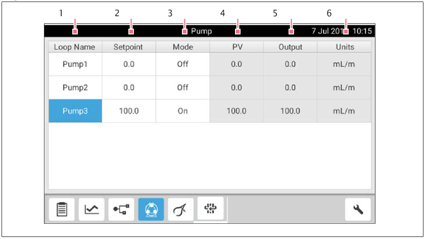
Figure 5. The user will reach this screen by clicking on the icon that is highlighted in blue (showing it is activated).
4.8 Controlling the pH (Consult with Lab Manager to see if Applicable):
- Consult with your instructor(s) or the lab manager to determine the correct concentration of sulfuric acid and sodium hydroxide.
- Mix the acid and base and place into the 250 ml glass containers located in the spring holders next to the glass reactor.
- Place antifoamer in one of the 250 ml bottles. if needed.
- Check with the lab manager for assistance in connecting the pumps and tubing.
- Enter the desired pH value in the Summary Window on the controller.
- The “lower left” icon opens the summary window (see Figure 6).
- The temperature, pH, Agitation, and 2-DO (dissolved oxygen) may be controlled from this window.
- In the Summary Window, enter the set point for the desired loop (e.g. acid or base).
- Set the mode to ON.
- The process variable (PV) displays the current data.
- The output displays the output of the controller for the loop.
- When the process variable equals the setpoint the output should go to zero.
4.9 Adjusting the Gas Flow:
- From the summary window, select Gas Flow. This will open the Sparge control window (see Figure 5).
- Enter a set point from 0-20 liters per minute in the top row, gas flow set point box. The value entered in this box represents the total flow of air and/or nitrogen.
- Once you have entered a value for the total flow, enter a set point for air and/or nitrogen. If you wish to have a mixture of air and nitrogen, enter a set point for the air that is less than 100%, the nitrogen flow will make up the difference to bring the total flow to 100 %.
- If you are only using air, enter the desired air flow in the Gas Flow set point box.
- O2 and CO2 gases are not typically available. If you wish to use these gases consult with the lab manager.
5. Saving Your Data to a Flash Drive:
- Select the Trend icon. This selects the data that you want to save.
- Select the + sign in the upper left of the trend window.
- This will open the loop selection window. Select the loop window and then select the loop you wish to add and then select the check icon. The loop you selected should be displayed in the trend window.
- Continue this procedure to add data loops/trend data. These are data that you want to export to your flash drive.
- Once you have selected all the loops that you wish to export, insert a USB drive into the USB port located in the rear of the bioreactor.
- Select export, enter a file name for your data, and then select the check icon.
- The software will create a “Bioflow” folder on your flash drive. The data are stored in a csv format. You can open these data in Excel, on your computer.

Figure 6. The Sparge control window, accessed from the Summary screen???
Before You Leave the Lab:
- Turn off the reactor heater.
- Turn off the main cooling water valve (see Figure 3).
- Label all chemicals with the contents, concentration, user’s name, and laboratory section.
- Save your data to a flash drive or it may be overwritten.
- Do not shut off the bioreactor.
- For the following steps, always consult with the lab manager beforehand.
- If you used nitrogen gas, make sure that the regulator is rotated to the left such that there is no outlet pressure.
- Close the main tank cylinder valve.! (see Figure 3)