UOL Distillation Column
Standard Operating Procedure
Introduction
Before using the equipment, familiarize yourself with safety precautions. Key safety issues are summarized in Section II. Figure 1 is a photograph of this laboratory apparatus.
Safety
- SAFETY GLASSES ARE REQUIRED WHEN OPERATING THE DISTILLATION COLUMN.
- Wear gloves when mixing alcohol feedstock.
- Since the column will become hot, use caution and wear insulated gloves when appropriate.
- Avoid flames or sparks while working with ethanol. Mix feedstock in a fume hood.
- THE COLUMN OPERATOR MUST REMAIN AT THE COMPUTER AND CONTROL CONSOLE WHILE THE COLUMN IS IN OPERATION.
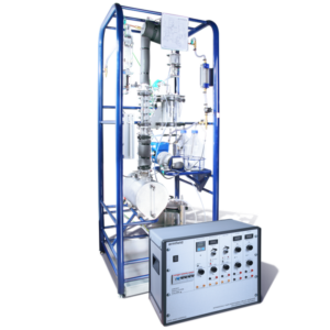
Figure 1. Overall view of the apparatus with the controller in the front.
Equipment / Procedure Overview:
General
- The distillation column takes about 45 to 90 minutes to reach steady state.
- Plan on shutting the column down by 4:30 pm to allow the feedstock to cool.
- Given the time required for startup and shut down you will want to pay particular attention to planning and preparation.
- First, operate the column by charging the reboiler with tap water only. Operate the column in total reflux to get a feel for the heater and reflux valve controls.
- Determine the type of solution you want to distill.
- Determine calibration standard requirements.
- Mix the feedstock and calibration standards.
- Proceed with the distillation process.
- Before operating the column, familiarize yourself with the location of the valves (Table 1 and Figure 1), flowmeters, and thermocouples.
- Temperatures are measured using type K thermocouples. Refer to the column diagram for the location of the thermocouples (Figure 2).
- Refer to the equipment photos for clarification of hardware descriptions.
- Refer to the Distillation Docs folder on the desktop for more information.
Valves
The valves are labeled as shown in Table 1.
Table 1. Valve Designation
| V1 Reboiler outlet to bottoms tank | V8 Dosing vessel – Not Used |
| V2 Reboiler Drain | V9 N/A |
| V3 Reflux sample | V10 Decanter / Tops drain valve |
| V4 Tops sample | V11 Bottoms product drain |
| V5 Condenser water flow control | V12 Tops products – drain to reboiler |
| V6 Manometer Valve – bottom of column | V13 N/A |
| V7 Manometer valve – top of column | V14 Cooling water to vacuum line – Not Used |
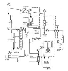
Figure 2. System schematic.
Figures 3 and 4 are screenshots of the Armfield software and the main GUI. Figure 5 shows the control console. Figure 6 shows the condenser drain tube and the distillation condenser water supply valve. Figure 6 shows the reboiler’s sight tube and the sample tube. Figure 8 shows installing tubing in the pump.
![]()
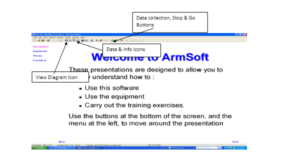
Figure 3. Menu bar enlargement and welcome screen
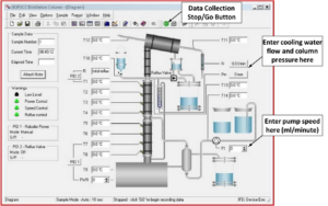
Figure 4. Screenshot of distillation diagram.
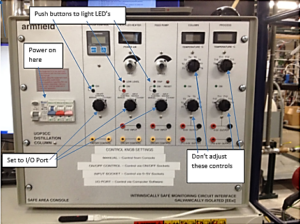
Figure 5. Control Console.
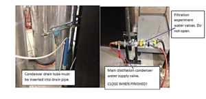
Figure 6. Condenser drain tube and distillation condenser water supply valve.
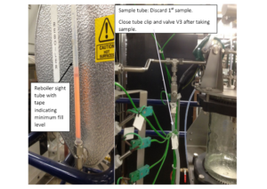
Figure 7. Reboiler sight tube (left) and sample tube (right).
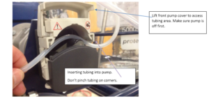
Figure 8. Inserting tubing into the pump.
Run the column with water
The following step is not necessary, but if you would be more comfortable with a practice run, follow the instructions in the paragraph below.
For your first experience with the column, you may want to skip the section on preparing the feedstock and calibration samples and start with the equipment startup procedure. Plan on spending the first lab period operating the column with water. This will allow you to get a feel for how the column is operated.
Filling the Reboiler and Preparing Feed Stock
Consult with your instructor or the lab manager and determine the concentration of alcohol you require in your feedstock. Use either pure or denatured ethanol or isopropyl alcohol and tap water. Use D.I. water to prevent scaling in the apparatus.
If you are doing a partial reflux experiment you will need a separate container for your feedstock. The feedstock is pumped to the column from a 5000 ml glass feed vessel. There is a second 5000 ml glass feed vessel that may be used for storing additional feedstock to be used during the day’s run. Do not use the second glass feed vessel for storing feedstock overnight. Place the cap with the siphon tube on the glass feed vessel you wish to use.
Fill the reboiler with water or feedstock as instructed by your professor/lab manager. Note the difference between the reboiler and the 5000 ml feed vessel. For total reflux experiments, you will not need a secondary vessel.
The recommended volume of solution to place in the reboiler is 5.5 liters. The reboiler must be filled with approximately 5.5 liters for the low-level alarm to clear.
Preparing Calibration Samples
Determine the range and number of calibration standards you will need to build a calibration curve. You will analyze your calibration standards using the densitometer or refractive index instruments. The lab manager will instruct you on the use of those instruments.
Storing feedstock and calibration samples
Make your calibration standards and store them in an appropriate container. Be sure to label your samples with the material, concentration, and group name. Consult the lab manager for assistance with storing your samples and feedstock.
Mix the feedstock and store it in an 8-liter Nalgene container. These containers are located in MEB 3520A on top of the cabinets. Label the container with your group name, the type of solution, and the concentration.
All flammable feedstocks must be stored in the flammables cabinet.
At the end of each lab period, you will need to drain the column and store your feedstock in Nalgene containers. Place the labeled containers in one of the flammables cabinets.
Equipment Startup Procedure
- Turn on the control console (Figure 5) by switching on the breaker switches. The up position is “on.” Turn on the Main breaker first and then the individual breakers. The gray switch is the main power, followed by individual breaker switches (blue=reboiler heater, red=feed pump/reflux valve, pink=console instrumentation).
- Ensure all dials on the control console for the Reflux Control, Reboiler Heater, and Feed Pump are turned to the “I/O Port” position. See Figure 5.
- Log on to the computer. The username is administrator, and the password is password.
- Open the UOP3CC software (the icon is on the Desktop).
- In the lower right-hand corner ensure “IFD: OK (F###)” is displayed. This indicates the computer and control console are communicating properly.
- Click on the “View Diagram” icon (the first icon on the right of the grayed-out cut/copy/paste icons). This will bring up the GUI, Graphical User Interface. See Figure 3.
COLUMN OPERATION PROCEDURE (Batch – Total Reflux)
- Ensure the following valves are CLOSED: V1, V2, V3, V4, V5, V6, V7, V8, V11, V12, V14, V15.
- Ensure that valve V10 is open. (note: there is no valve V9 or V13).
- Verify that the white tubing – condenser drain line- is securely inserted into the blue drain stand-pipe located behind the distillation control module. See Figure 6.
- The reboiler incorporates a level sensor. If the liquid level in the reboiler is not at least equal to the height of the orange tape on the reboiler sight tube, approximately 5.5 liters, the software will not allow the reboiler to heat. The lack of sufficient liquid in the column is indicated by the low-level warning light in the GUI. See Figure 7.
Filling the reboiler
- Remove the fill cap on the top of the reboiler and, using a funnel, add approximately 5.5 liters of tap water or feedstock to the reboiler. Approximately 5.5 liters is the minimum amount of liquid required to clear the low-level alarm on the reboiler.
Turning on the Condenser Cooling Water
- Turn on the main condenser cooling water valve located behind the column at the bottom of the water pipe (Red handle ball valve). Do not fully open the valve! Only open the valve about a quarter of the way. Note the yellow handle ball valve next to the Red Valve, DO NOT operate the yellow valve, it is for the filtration experiment. See Figure 6.
- Adjust valve V5 to set the desired condenser cooling water flow rate; a good starting point is 1000 ml/min. The typical operating range is 1000 – 1800 ml/min. Adjust this parameter as required.
Setting the Controller
- On the controller, set the Reflux Control, Reboiler Heater, and Feed Pump to the I/O port and push in the black button above each knob to set the controller to on. The LED above the control knob should light for each section listed above. See Figure 5.
- The Column and Process sections on the controller are for manual operation without a computer. You do not need to adjust these controls.
Heating the reboiler (PID 1)
- The reboiler may be operated in either manual or PID (automatic) mode. Click on the PID 1 icon on the main graphic display. This will open the reboiler heater PID controller window.
- When operating in manual mode you must take care not to allow the column to overheat. It is recommended that you operate the reboiler in automatic mode.
- Set the mode of operation to automatic.
- Enter the desired set-point. Note that the set-point is the temperature of thermocouple #7, not the temperature of the reboiler liquid. The recommended starting set point is 85°C. You will adjust the set point as you develop your method. Do not adjust the Proportional band, Integral time, or Derivative time.
- Click on apply, and then OK. Note the PWR (power) level display is reading 100%. This will gradually reduce as the temperature set-point is reached.
- The warning indicators on the left side of the GUI (Graphical User Interface) should all be green except for the low-level indicator on the top. If the low-level indicator is red, this indicates that the reboiler does not contain enough liquid. If the other warning lights are not lit green this indicates that the “on” button for that function is not depressed on the control module. See Figure 4.
Reboiler Overflow / Feed Pre-Heat Valve V1
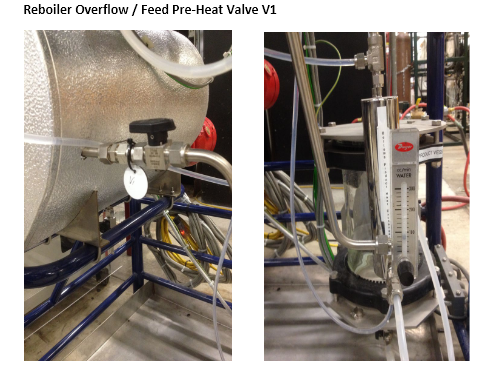
Figure 9. Reboiler overflow/feed pre-heat Valve V1 (left) and rotameter (right).
- With the reboiler overflow/feed pre-heat valve V1 open, liquid in the reboiler that exceeds the level of the overflow valve will flow through the reboiler overflow rotameter, through the column feed pre-heater and into the bottom vessel (Figure 9).
- In addition to preheating the feed, setting this valve to the open position allows for the measurement of the bottoms vessel feed flow rate by reading the flow on the rotameter. The rotameter incorporates a valve that allows for regulation of this reboiler overflow to the bottoms vessel (Figure 9).
- Valve V1 may be set to the closed position when operating the column in total reflux. Valve 1 (V1) is kept closed when running in total reflux.
- Valve V1 is often set to the open position when operating in partial reflux.
- Be sure to check with your instructor/lab manager to determine how this valve should be utilized.
Reflux Valve Operation
- The reflux valve may be operated in either total reflux (OFF) or Manual Mode. In manual mode (partial reflux), the operator may set the reflux ratio to the desired setting.
- Do not use automatic mode – it does not function. For total reflux, the setting is OFF.
- Disregard all parameters in the automatic operation section of the PID controller window.
Setting the Reflux Valve for Total Reflux (PID 2)
- Initially, you will want to operate the column in total reflux mode.
- To do this; set the Mode of Operation to OFF, click apply, and then OK.
Setting the Reflux Valve for Partial Reflux using Manual Mode Control (PID 2). Note in CH EN 3702, you will be doing Total Reflux
- Click on the PID2 icon and select manual mode.
- Enter a ratio in the Reflux Ratio Initial window.
- Do not enter a value in the rate of change window.
- Click on the start button.
- Click on apply and then ok.
- To stop the reflux valve from operating, click on the stop button.
In manual mode (partial reflux) the reflux valve switches at a frequency of 10 seconds. Adjusting the reflux ratio controls the distillate distribution, sending distillate to either the column or the “tops” container, within the 10-second interval. For example, for a ratio of 4:1, condensate will be directed to the column for 8.0 seconds and to the top product receiver for 2.0 seconds.
4 + 1 = 5 → 10/5 = 2.0 → 4 x 2.0 = 8.0 seconds to the column
By entering a reflux ratio of 2:1, the reflux valve with switch the flow of distillate to the tops vessel for approximately 3.3 seconds and then to the column for approximately 6.7 seconds.
A value of 3:1 = ~2.5 secs to tops, ~ 7.5 secs to column.
Another example: By entering a value of 1 in the “initial “window to make the ratio 1:1, the reflux valve will switch every 5 seconds, with 5 seconds of flow going into the column and 5 seconds of flow going into the tops container.
Fill the feed bottle
Verify that one of the 5000 ml feedstock bottles is filled with your feedstock, as described earlier. The feed pump operating rate range is between 0 and 300 ml/min. This will not be necessary if you are doing total reflux.
Pumping the feedstock
Insert the tubing into the pump
- Verify that the pump speed is set to zero. Enter the pump speed (0) in the drop-down window next to the F1 symbol on the GUI.
- Lift the top of the peristaltic pump cover and insert the tubing into the peristaltic pump making sure not to pinch the tubing and then close the cover. See Figure 8.
Note the path of the feed line: The feed line connects into a tee fitting; the outlet of the tee connects to the bottom of the bottoms product heat exchanger which allows for pre-heating of the feedstock before it enters the column. The feed exits the top of the bottoms product heat exchanger and is fed to the column. The feed temperature is measured at the center feed location, see T14 on the GUI.
Select the Column Feed Port:
Typically the column is fed by connecting the pump outlet to the center feed location as labeled on the column. Do not adjust the feed port unless instructed to do so by your instructor or the lab manager.
Setting the Pump Speed/Flow Rate:
It is advisable to calculate the feedstock flow rate before operating the column. Typically the feedstock flow rate is between 5-50 ml/min. This is not a recommended flow rate, just a typical range. If the feed flow rate is too high, the flow rate out of the reboiler overflow valve may exceed the range of the reboiler overflow rotameter.
The symbol F1 on the distillation GUI represents the pump. Enter the pump speed in the drop-down window next to the F1 symbol. The units are milliliters per minute. The range is between 0 and 300 ml/min.
Manometer Reading on GUI – Pm
The window on the GUI next to the letters Pm allows you to manually enter the pressure drop across the column as read from the glass manometer located on the left side of the distillation column frame. You may also use a handheld Dwyer electronic manometer to measure the differential pressure across the column. Consult the lab manager for access to the Dwyer manometer. Whatever value you enter will be saved to the data file. The computer does not automatically update this information. Discuss this measurement with the lab manager.
Cooling Water Flow Reading on GUI – Fr
The window on the GUI next to the letters “Fr” allows you to manually enter the cooling water flow rate, as read from the cooling water flowmeter. Whatever value you enter will be saved to the data file. The computer does not automatically update this information.
Recording Data
The system will not record data until you press GO.
- To begin recording data, press the green “GO” button on the GUI (above the condenser on the GUI of the column). See Figure 4.
- Press “Stop” when you wish to end data collection.
Operation Guidelines
- As the column heats, you will begin to see vapor rise up the column and start to see bubbling on the lower trays. You will also see liquid flowing from the condenser into the decanter, then back to the column through the feed pipe in the rear of the column above the top tray.
- Adjust the reboiler heater set point as required to get a consistent amount of bubbling on the trays without flooding the column.
A simple definition of column flooding is “the column is flooded or starting to flood if the liquid level in the lower tray(s) has reached the bottom of the tray above it.”
To stop flooding, lower the heater set point. Adjusting the column temperature to the optimum level is as much an art as a science. The column has reached thermal equilibrium when the temperatures in the column are stable. Liquid samples can be taken using the procedures under “Taking Measurements”
TAKING MEASUREMENTS
The sample liquid is hot! Use caution when taking samples. Always wear safety glasses. Wear leather gloves and a lab coat as needed.
Make sure you click on the GO button to begin data collection. Select the Stop button to stop the data collection. Before taking measurements, discuss measurement and sampling procedures with your instructor or lab manager.
Column Pressure Drop
Column pressure drop is measured by the water manometer on the left of the column. VALVE OPENING AND CLOSING MUST BE DONE IN THE ORDER BELOW TO AVOID GETTING VAPOR IN THE MANOMETER. Consult with the lab manager.
- Open valve V6.
- Open valve V7.
- Take a reading.
- Close valve V7.
- Close valve V6.
A note on taking samples
- Tops products samples may be taken by opening V3 and releasing the tube clip. Discard the first sample as it will be old.
- Tops products samples may also be accessed through V4 located at the bottom of the tops product vessel.
- Bottom samples can be accessed from the reboiler drain valve, V2, located at the bottom of the reboiler, they may also be taken from the bottoms vessel using valve V2 and the peristaltic pump to drain the bottoms vessel.
- Samples from each tray may be taken using a syringe. Consult the lab manager for instructions on taking tray samples.
Viewing the Data
- To view the data, click on the View Table Icon.
- To view the data as a plot, click on the View Graph icon.
- To modify the way the data are plotted on the graph, select Format – Graph Data.
- The graph data are of limited value, the tabulated data are the data that you will export to Excel.
Saving and Exporting the Data
- The computer is not on the network – save your data to a flash drive after each run.
- DO NOT plug your flash drive into the USB ports on the front of the computer, doing so will lock up the computer and you will need to reboot the system.
- Connect your flash drive to the USB extension cable that is visible in front of the control console.
- If you close the software without saving your data, the data will be lost!
Once you have collected data, you must save it as an Excel file before exporting it.
- To save the data, click on the Stop icon to stop data collection. Go to File/Save As, and then click on the drop-down menu to select the Excel file type. Select Save.
- Save your data as a .vts file if you wish to view it later in the distillation software. Only files saved as a .vts file can be opened by the distillation software.
System Shutdown
- Begin shutting down the system by no later than 4:15 pm. It will take about 30 minutes for the feedstock to cool down enough to safely store it in the Nalgene containers.
- On the main control unit, turn off the three individual breaker switches and then turn off the main power switch.
- Once the feedstock has cooled to 80°C, drain the contents of the reboiler into an 8-liter Nalgene container using the valve located beneath the reboiler. Use caution and wear insulated gloves when draining the reboiler. The feedstock is HOT. The lab manager can work with you.
- If there is liquid in the bottoms vessel, pump it into a Nalgene container using the peristaltic pump located next to the column.
- Close the main condenser water cooling valve (ball valve) located behind the column.
- Save your data to a flash drive.