Thermoelectric Human Power
Summary
To generate usable energy, all we need is a temperature difference. In this module the temperature difference between human hands and cold water or ice is used to create electricity and demonstrate the use of a temperature difference to extract usable energy.
General Information
Essential Questions
- How can a temperature difference be used in power generation?
- What are thermoelectric devices?
Materials & Methods
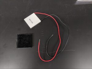
- A set of 4 cm x 4 cm peltier devices
- 4 are needed to turn on a LED using a block of ice and typical human hands; about 8 are needed if just using cold water.
- Example: http://a.co/8moUUM2
- A set of 4 cm x 4 cm heat sinks (optional)
- Only needed if using cold water for the cold sink; if using an ice block , these are not needed.
- Example: http://a.co/0hNBTZy
- Red LED
- Red LEDs require the lowest voltage to be visible to the human eye, but other colors may be used (just be aware they will require either more peltier devices or a greater temperature difference).
- Example: http://a.co/5v9EdYc
- 1 kᘯ resistor (Optional for quantitative activity)
- Any significant resistor of known resistance should do.
- Wire nuts, alligator clips, or solder to connect wires from peltier devices.
- Shallow plastic container
- If using cold water we use something that is approximately the size of a cookie sheet.
- If using ice, we use a small tupperware to freeze the ice, just large enough to fit four peltier devices.
- Example: http://a.co/gfPenvK
- Tap Water and a freezer, and/or Ice
- Multimeter or voltmeter, if quantitative measurements are desired.
- For example: https://www.amazon.com/s?k=multimeter&ref=nb_sb_noss_2
https://www.amazon.com/s?k=mini+voltmater&ref=nb_sb_noss_2
If you buy a mini voltmeter make sure you get the three wire version. A 3D printer file for a case for mini voltmeter may be found here:
https://drive.google.com/open?id=1QjPgi2Qpvmdh70YFA0drcueebTy-UnBz
- For example: https://www.amazon.com/s?k=multimeter&ref=nb_sb_noss_2
- Non-contact thermometer or thermal camera (optional)
Assembly:
- If using an ice block: Fill your container with water and put it in a freezer as soon as possible.
- Determine which side of the peltier device should be heated in order to create a positive voltage in the red wire.
- Most peltier or thermoelectric devices have their model number printed on the same side, and so by orienting one you can orient them all. For the devices used in this work, heat should be applied to the side without the printed model number.
- If you do not have a multimeter: you could set them all up and then continue with these methods and test with the LED; if it does not light, just switch the wires into the LED.
- If you do have a multimeter: Attach the multimeter’s black lead to the black wire of the peltier device and red to red; set the multimeter to read DC voltage. Set the peltier device on a room-temperature table and place your hand on top of it. If your warm hand causes the voltage to go up, the side of the peltier device you are touching should face up in the final design. If the voltage goes down, the side your hand is in contact with should face down.
- If using cold water: Attached a heat sink to the down side of the device (the side that should be the cold side). These will keep the water from going over the top of the device and facilitate heat transfer. A small amount of epoxy or super glue can be used to secure the heat sink to the device but is not really needed; just be sure to remove as much air from the junction as possible, as it will otherwise inhibit heat transfer.
- Wire the peltier devices in series using alligator clips, wire nuts, or solder. If using cold water the following design id needed:
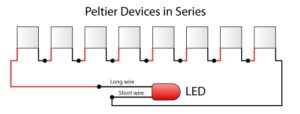

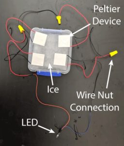
If using ice, then only four devices are needed in series:
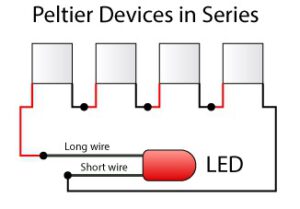

- Make sure black wire from one device attached to the red wire of the next device, and that all devices are oriented with the correct face up. In this way the voltage from each device will add up enough to light the LED at about 2 V (if they were in parallel instead the current would add up and the voltage would be too low).
- The red wire on the first device should connect to the longest wire on the red LED, and the black wire on the last device should connect to the short wire on the LED. A red LED is used because it requires less voltage (and energy) to light up that other colors. It takes about 6 of the inexpensive peltier devices from our parts list with heat sinks to light one red LED, with the temperature difference between a hand and ice water. You can add more devices to account for students with abnormally poor circulation (we typically use 8, with cold water)
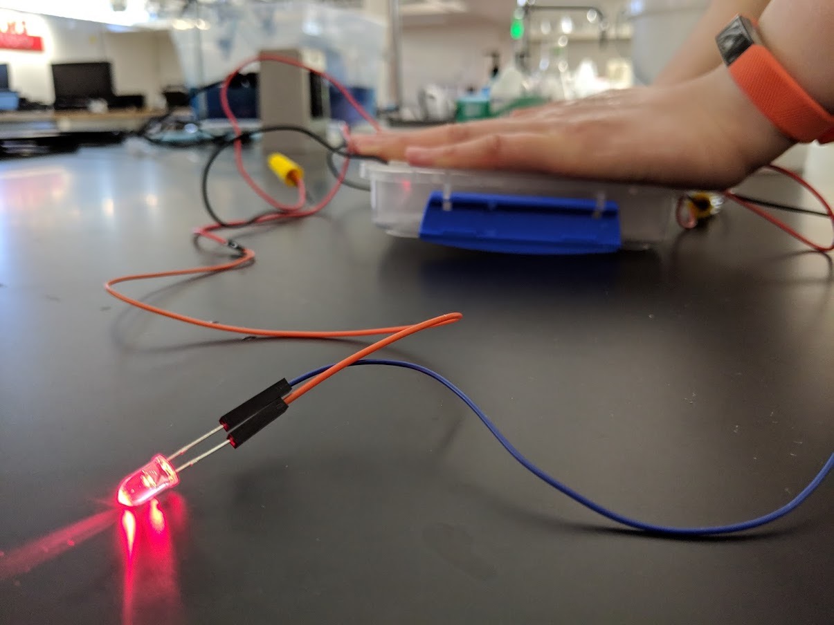
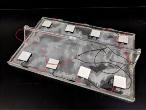
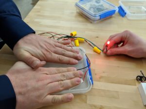
- If using cold water: Place the devices in a shallow container. Fill the container up with ice water to the level just below the height of the heat sinks (about 1 cm). We laser cut our device, and placed the LED in a tube in the middle as shown in the following photograph, but that is not necessary.

- If using an ice block: Place the devices directly cold-side down on the ice.

Instructional sheet to include in kit:
Background for Teachers
- Due to the laws of thermodynamics (https://en.wikipedia.org/wiki/Laws_of_thermodynamics) heat will flow from a high source to a low sink, and useful energy can be extracted from that flow of heat. This flow through a solid is called thermal conduction. Having a high temperature alone, without any cold sink into which that energy can flow, is not enough; the flow of energy is needed to produce energy that we can use to do useful work, like create the electricity that turns on our lights.
- Thermoelectric devices act like pumps for electrons that are powered by a temperature difference between their two faces. Peltier devices also work this way but they are typically used in the reverse manner; by flowing electrons through them, they produce a temperature difference. This effect is called the Thermoelectric effect (https://en.wikipedia.org/wiki/Thermoelectric_effect)
- Semiconductors used in the devices have charge carriers that move from the hot to cold side of their particular semiconductor material, both n-type and p-type. This process is described by the seebeck effect: http://searchnetworking.techtarget.com/definition/Seebeck-effect.
- In the n-type semiconductors an electron donor has been added to a semiconductor, like silicon. When one side is heated this donor passes electrons to the colder side of the material (note that, due to convention, positive electric current goes the opposite direction to the flow of electrons). The other semiconductor is a p-type semiconductor, meaning it has an electron acceptor mixed into it. When heat is added to the p-type semiconductor, it effectively transports a positive charge to the cold side of the material.
- If the n-type and p-type semiconductors are placed as shown in the diagram below, they can effectively transport electrons through a wire, leading to a voltage which may be used to create power. Note that electrical current would travel
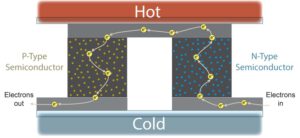

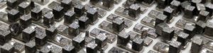
- Inside each peltier devices, there are many of these junctions in series, in order to create enough voltage. Below is a photograph of the interior of one of the peltier devices and the p and n semiconductors may be seen. Many were broken when the device was opened, but they would otherwise look like the diagram above, with two pillars of differing semiconductor types.

Electric Power
Electrical power can be expressed in terms of voltage and resistance. According to Joule’s First Law, power can be expressed by the following:
![]()
Where P is power, I is electric current, and R is resistance. To obtain power in terms of measured voltage across a know resistance, R, we must also use Ohm’s Law:
![]()
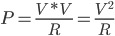
Solving for I and substituting into Joule’s First Law we obtain an equation for power in teams of what is known in this module, voltage and resistance:
![]()
Using the voltage, V, value across the 1 kΩ resistor, R, the amount of power generated by the person blowing into the turbine can be determined. For example, if the voltmeter read 2.0 V, we could calculate the power generated to be 4 milliwatts by:
![]()
Instructional Procedures
Demonstration Activity:
- Give background information on peltier devices and energy from temperature differences. You may wish to use this presentation:
https://docs.google.com/presentation/d/1I44a3Tj0IiUNMAhrWUxfbfN244g2JVW4n81M0r7hz0A/edit?usp=sharing - Give out kits to teams of 3 or 4, or gather students around a single demonstration device.
- Have students set up their devices as described above, connected to the LED.
- Spread the devices out as much as possible so that they aren’t overlapping hands when trying to light the LED.
- Allow the devices to melt into the ice for about two minutes before use; that will create better contact with the cold side by filling the interface with a layer of liquid water.
- Instruct them to warm up their hands by rubbing them together, and, on the count of three, place their hands as flat as possible on a peltier device. To get the LED to light the students need to have as much contact as possible to the warm side of the devices. One to 4 people could light a LED. If using more than two people, a larger ice block may be needed so that hands may be spread out sufficiently.

- Once they place their hands on the devices, they should generate enough power to light the LED.
- Discuss with the students material from the Background for Teachers
- How to get more power (more devices or higher temperature). You could also try to light a LED that requires more power, such as a blue LED.
- Why do you need a temperature difference?
- How does this demonstration relate to generation of electricity for a society?
- Why can’t we get energy by just heating up the devices?
Quantitative Activity:
- After the demonstration activity, pass out the multimeters and 1 kΩ resistors.
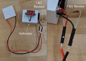
- Instead of connecting to the LED, connect the red wire from the peltier devices to the voltmeter’s red (+) wire and the black wire to the black (-) wire of the voltmeter.
- Now connect a known resistor between the red and black wires. We did so through both sides of a jumper’s female ends, but the same could be done with alligator clips.

- The voltmeter should now be measuring the voltage across the resistor.
- Repeat the steps used to get the LED to turn on but now while measuring voltage.
- Students may record the max voltage they can obtain with one device and see how, when they are wired in series the voltages add together.
- Have the students calculate power using the equation given in the Background for Teachers:
- Once they know approximately how much energy can be obtained from one thermoelectric device, you may ask them to calculate how many would be needed to power a 50W light bulb or match the capacity of an average geothermal plant (100,000,000 W).
Instructional Options:
- Show the students the voltage from one peltier device and the voltage needed to light the LED, and ask them to calculate number of peltier devices needed to light the light, before you assemble the circuit. Talk about the difference between series and parallel circuits.
- Demonstrate that an opposite voltage can be obtained by putting hot water in the container (being careful not to create a burn hazard).
- Show the students that if you attach a battery to the wires of the peltier device, you will heat one side and cool the other. Connect to how this effect may be used in temperature control and in keeping electronics cool. You may measure the temperature with the non-contact thermometer.
- More advanced student may develop a power versus temperature difference curve for the thermoelectric devices, by applying known temperature differences across the device and recording temperature. It would be best if one of the sides was kept on ice so that you can know it is zero. The temperature of the other side would need to be estimated from a quick IR thermometer reading.
Acknowledgements
Supported by funding from Utah’s Governor's Office of Energy Development, and the US Department of Energy’s Utah FORGE project.