MPTL Plug Flow Reactor SOP
Standard Operating Procedure
1. Introduction:
There are several plug flow (tubular) reactors in the Meldrum Process Technology Laboratory and the Unit Operations Lab. Figure 1 is a photograph of one of them. The figure shows a packed-bed reactor (different reactors have different geometries and packing). Reactors like this approximate the behavior of plug-flow reactors (PFRs). The flow field in these tubular reactors may be approximated as having a plug flow profile (as in a uniform velocity profile experienced in turbulent pipe flow). There is no radial variation in the reaction rate.
Do not proceed with testing without following all safety procedures. A basic list of safety considerations is provided in Section II of this SOP.
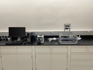
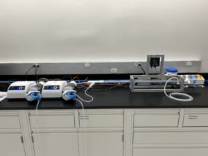
Figure 1. Plug flow reactor.
2. Safety
- All students must wear safety glasses when working in the lab.
- Never leave this equipment operating unattended.
- Mix all chemicals in a fume hood.
- All chemicals, solutions, and standards must be stored in a sealed container. The container must be labeled with the chemical(s) name (not formula) and concentration, the operator/user’s name, hazards, and the date of storage.
- All chemical containers must be sealed when not in use.
- All unwanted material must be placed in an appropriate container. The container must be labeled “Unwanted Material”. The label must include the chemical(s) name and concentration, the user’s name and contact information, and hazards. If you have questions regarding labeling unwanted materials, consult with the lab manager.
- Only pure water (no additives or contaminants) can go down the drains.
3. Equipment Description
The tubular reactor experiment incorporates the following equipment:
- Masterflex peristaltic pumps: These pumps have a switch on the rear panel; they must be set to external for the computer system to control the pumps (Figure 2).
- PVC reactor tube filled with glass beads and fitted with type T thermocouples Figure 3).
- Opto22 Control System: Data are sampled every second and stored in an Excel-compatible file on the Desktop (in a folder labeled “Data” or similar). See the section on viewing your data for more information. Save your data to a flash drive. The computer is not on the network. For more information on saving data, see the “How to View and Save Data in Excel” section.
- Sensorex conductivity measurement system (Refer to Figure 3 – readout devices may vary). The conductivity range and resolution are labeled above the conductivity meter’s digital display
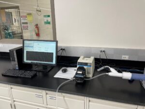
Figure 2. Masterflex peristaltic pump. |
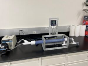
Figure 3. Reactor tube and conductivity sensor. |
4. Procedures
- Determine what chemicals, calibration standards are required, and measurements you will need to make.
- Determine the desired inlet flow rate for your solution reactants.
- Refer to the section on pump specifications and tubing to help determine what tubing is appropriate for your flow rates. Be sure to use only Masterflex tubing. If you are unsure about which tubing to use, check with the lab manager. The smaller the inner diameter of the tubing the lower the flow rate.
- Pumps may be calibrated using a graduated cylinder/calibrated bucket and a stopwatch. Calibration can either be done using the pump’s RPM (internal pump controls), or percent power (external pump controls – using Opto22 control interface).
- Install the tubing through the peristaltic pumps. Depending on the model of the peristaltic pump being used, it may be possible to use the same size tubing in both heads of a dual–head pump to achieve two identical flow rates – but you should calibrate each pump, nonetheless.
- Reactor setup options:
- Calibration setup (Refer to Figure 4):
- Attach one tube to the valve connected to the outlet of the CSTR. This will allow pumping the solutions or conductivity standard into the tee/probe assembly, filling it from the bottom (without going through the reactor). The valve to the conductivity probe is closed.
- Make sure is connected to the outlet at the top of the tee located to the left of the valve used to test conductivity. Insert the other end into the waste container.
- Close valve 1 and open valve 2.
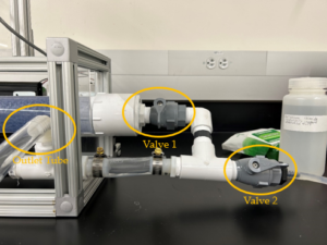 Figure 4. Conductivity Setup. Notice the positions of each valve, valve 1 must be closed and valve 2 must be open. You can refer to Figure 3 to see where this fixture is in the apparatus.
- Reaction setup (Refer to Figure 5)
- Attach tubes to both of the inlet lines located on the left side of the reactor.
- Make sure the outlet tube (larger tube) is connected to the outlet at the top of the tee located to the left of the 2 valves used to test conductivity. Insert the other end into the waste container.
- Verify that the valve 1 is open and valve 2 is closed.
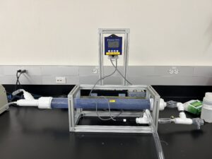 Figure 5. Reaction Setup.
- Calibration setup (Refer to Figure 4):
- Power up all equipment (the computer should be on):
- Switch on the power to each pump by using the grey toggle switch located on the front panel for older pumps or the power switch in the back for newer pumps.
- The Sensorex conductivity module does not have a switch. It is always on.
- Do not touch the opto22 control hardware located behind the computer.
- Using the conductivity measurement system:
- The conductivity probe is enclosed in a tee fitting connected to the outlet of the PFR. The probe connects to the conductivity transmitter (Sensorex Model CX 100) mounted on the PFR frame.
- Do not attempt to adjust the calibration setting on the CX105 conductivity meter. You need to verify if the conductivity system is working properly by using the provided conductivity standard (following protocols 9b to 9f). Consult the lab manager if you feel that the meter requires adjustment.
- Calibrating chemical solutions:
- In addition to testing the reliability of the conductivity meter using the standard, you will need to prepare individual concentrations of your reactants and products, and then use the conductivity system to build a calibration curve of concentration versus conductivity.
- Set up a pump and the reactor as depicted in protocol 6a.
- Prepare just enough of the solutions that you prepared for calibration or the conductivity standard to fill the tubing and the tee. This volume is typically about 200ml.
- Pump the solution or conductivity standard through the reactor. Allow any excess liquid that was in the reactor to drain out into a waste container (Once the conductivity stops changing significantly all excess liquid has been removed).
- Make sure to rinse the system out with DI water between different solutions.
- After the calibration curves are obtained and you have also tested system reliability with the standard, set the reactor to the reaction setup as depicted in protocol 6b.
- Determine the amount of feedstock you will require.
- Mix all chemicals/feedstock dilutions in a fume hood.
- Place your feedstock in 8-liter Nalgene containers available in the “A” lab on the shelf above the chemical storage cabinets (Senior Lab).
- Feed the outlet stream of the system into a different Nalgene waste container.
- Verify that the feed and drain pumps are connected.
- For determining residence time, there is a syringe upstream that will allow you to inject a pulse.
- Proceed with your experiment using the desired flow rates as previously determined.
5. How to view and save data in Excel
- Do not try to view/open your data while the system is running. This will cause it to stop data collection.
- Save data to a flash drive after each trial.
- If you have any questions, please ask for assistance.
If you are running one trial:
- Once all your required data have been collected, exit the Opto system.
- Open Excel, click “Open” and navigate to the correct data folder on the desktop (labeled “Data” or something similar).
- At the bottom of the Excel window, click on the drop-down window and select “All Files”. This will display the data files collected, organized by date.
- Double-click on the file you wish to open. The Text Import Wizard will open.
- Select Delimited. Then click Next. Then select Comma Delimited and click Next. Select the General Data format option and click Finish. The data should now be displayed in Excel
- Save your data to a flash drive by clicking “Save As” and selecting your flash drive as the destination. Ensure that you label your data properly and thoroughly to avoid confusion.
- Eject the flash drive.
- Follow the rest of the shutdown procedure specified in the equipment SOP (see the section labeled Shutdown, below).
If you are running several trials in one day:
- Leave the Opto system running.
- Open File Explorer and navigate to the correct data folder, on the desktop (labeled “Data” or something similar).
- Organize/sort by date if you have not already done so. Your data should appear at the top of the list.
- Right-click on your data file and “cut” the file (or press Ctrl X after clicking once on the file).
Note: this will effectively cut the data that were collected up to that point into a file and begin a new data collection (a new file will be created with the same name as the file you cut) as soon as it is cut.
- Paste the cut file to a flash drive and rename it with a proper label. Ensure that you are labeling your data thoroughly to avoid confusion.
- Eject the flash drive and save it to your personal device.
To open in Excel on your personal device:
- Open Excel. Next, click File/Open and navigate to the saved data on your flash drive or device.
- At the bottom of the Excel window, click on the drop-down window and select All Files. This will display the data files collected, organized by date.
- Double-click on the file you wish to open. The Text Import Wizard will open.
- Select Delimited. Click Next. select Comma Delimited, and then click Next. Select the General Data format option and click Finish.
6. Shutdown
- Drain the reactor and store any solution you wish to save in a properly labeled Nalgene container. Consult the lab manager regarding chemical storage.
- Flush the system with DI until the conductivity meter reads <100 microsiemens, and then drain and dispose of the water. Confirm disposal protocols with the lab manager.
- Label all containers, following appropriate labeling protocols.
- Properly dispose of any unwanted material. Consult the lab manager for guidance.
- Switch off the power to the pumps. Either place the toggle switch in the center for older pumps or flip the power switch on the back of the pump for newer pumps.
- Do not attempt to switch off the Sensorex conductivity module.
- Exit the Opto control software. Do Not shut down the computer.
- Save your data to a flash drive. The computer is not on the network.